14
1. Use the MC4 EVO2 PV connectors delivered with the inverter. If the PV connectors are lost or
damaged, purchase the connectors of the same model. The device damage caused by
incompatible PV connectors is beyond the warranty scope.
2. Before connecting DC input power cables, label the cable polarities to ensure correct cable
connections. If the cables are connected incorrectly, the SUN2000 may be damaged.
3. Measure the voltage at the DC input end using a multimeter. If the voltage is a negative
value, the DC input polarity is incorrect. Correct the polarity. If the voltage is greater than
1500 V, too many PV modules are configured to the same string. Remove some PV modules.
4. For models of the crimping tool and removal wrench, use the recommended model or
contact your Staubli dealer.
5. Connect the PV string connector to the inverter connector, and then pull back the PV string
connector along the axial direction to check whether the connectors are securely connected.
6. The connector must be securely connected. Damages caused by improper connection are not
covered under the warranty.
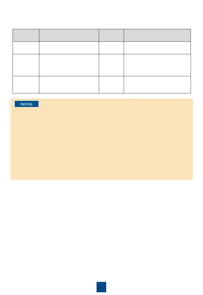
For example, if the number of input routes is 9–14, the DC input terminals are selected as
follows.
PV1, PV2, PV3, PV4, PV6, PV8, PV9,
PV11, PV13 and PV14
PV1, PV2, PV3, PV4, PV5, PV6, PV8,
PV9, PV10,
PV1, PV2, PV3, PV4, PV5, PV6, PV7,
PV8, PV9, PV10,
 Loading...