18
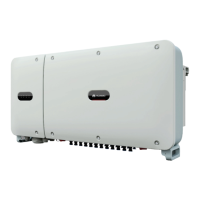
1. Turn on the AC switch between the solar inverter and the power grid.
2. Set DC SWITCH 1 (MAIN SWITCH) at the bottom of the solar inverter chassis to ON. When
you hear a click, the switch is ON.
3. Check the status of the PV connection indicator. If it is steady green, set DC SWITCH 2 and
DC SWITCH 3 to ON.
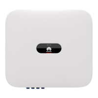
4. Observe the LED indicators to check the operating status of the solar inverter.
•
Before turning on the AC switch between the solar inverter and the power grid, check that
the AC voltage is within the specified range using a multimeter set to the AC position.
• Do not turn the DC switch to the unloaded position .
Status (Blinking Fast: On for
0.2s and Off for 0.2s; Blinking
Slowly: On for 1s and Off for
1s)
At least one PV string is properly connected,
and the DC input voltage of the corresponding
MPPT circuit is at least 200 V.
If the alarm/maintenance indicator is red, an
environmental fault at the DC side of the solar
inverter is generated.
The solar inverter disconnects from all PV
strings, or the DC input voltage of all MPPT
circuits is less than 200 V.
The solar inverter is in grid
If the alarm/maintenance indicator is red, an
environmental
at the AC side of the solar
inverter is generated.
The solar inverter is not in grid
The solar inverter receives communication data
normally.
The solar inverter has not received
communication data for 10 seconds.
Alarm/
Maintenance
indicator
A major alarm is generated
If the PV connection indicator or grid
connection indicator is blinking green fast,
troubleshoot DC or AC environmental faults
as instructed by the SUN2000 app.
If the PV connection indicator and grid
connection indicator are both not blinking
green fast, replace components or the solar
inverter as instructed by the SUN2000 app.
A minor alarm is generated.
A warning alarm is generated.
Local maintenance succeeds.
The solar inverter is in local maintenance or
shuts down over a command.
 Loading...