(1) DC input terminal group 1 (PV1
controlled by DC SWITCH 1)
(2) (Optional) Screw hole for DC switch 1
(3) DC switch 1 (DC SWITCH 1)
(4) DC input terminal group 2 (PV9
controlled by DC SWITCH 2)
(5) (Optional) Screw hole for DC switch 2
(6) DC switch 2 (DC SWITCH 2)
(7) DC input terminal group 3 (PV15
controlled by DC SWITCH 3)
(8) (Optional) Screw hole for DC switch 3
(9) DC switch 3 (DC SWITCH 3)
(12) Communications port (COM)
(13) Hole for the AC output power cable
(14) Hole for the tracking system power cable
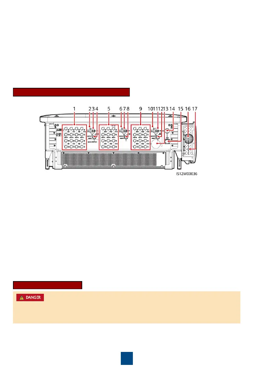
(1) DC input terminal group 1 (PV1
controlled by DC SWITCH 1)
(2) (Optional) Screw hole for DC switch 1
(3) DC switch 1 (DC SWITCH 1)
(5) DC input terminal group 2 (PV9
controlled by DC SWITCH 2)
(6) (Optional) Screw hole for DC switch 2
(7) DC switch 2 (DC SWITCH 2)
(9) DC input terminal group 3 (PV15
controlled by DC SWITCH 3)
(10) (Optional) Screw hole for DC switch 3
(11) DC switch 3 (DC SWITCH 3)
(15) Communications port (COM)
(16) Hole for the AC output power cable
(17) Hole for the tracking system power cable
Port Description (Automatic DC Switch)
DC Switch Description
The DC switches automatically turn off when a fault occurs in the inverters (LED4 is steady red,
and the three DC switches are OFF). In this case, contact your technical support. Do not turn on
the DC switches by yourself.
 Loading...