28
Primary Voltage Secondary Voltage (±5%)
380 207
415 221
440 214
480 234
575 206
600 215
Note: The secondary voltage listed in the transformer is based the transformer being used at
full capacity. Because there is essentially “no load” on the transformer, the secondary
voltage will be higher than the voltage listed on the transformer. This “regulation” varies
from 8.4% to 12% depending on the primary voltage and the transformer used.
Check the Hi-Limit Thermostats:
1. The unit is supplied with safety hi-limit thermostats mounted on the plate that holds
the heating chamber in place. In single phase units, these thermostats allow the power
from one phase of the terminal block to flow to the heating element. If the hi-limit
thermostat fails it will not supply the heating element with power and therefore the
heating element will not turn on and produce heat. In three-phase units, the
thermostats are wired in series to a magnetic contactor coil. If any hi-limit thermostat
fails it will not supply power to the contactor coil and therefore no power will be
supplied to any heating elements.
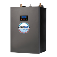
2. For single-phase units, check the voltage between the left-hand metal connection point
of the thermostat and the metal plate. If shrink-wrap is present around the metal
connection point to the hi-limit thermostat, cut back the shrink-wrap with a knife to
expose the metal connection. A voltage reading around 120V should be indicated
since this component is being fed by one leg of the electrical power coming off the
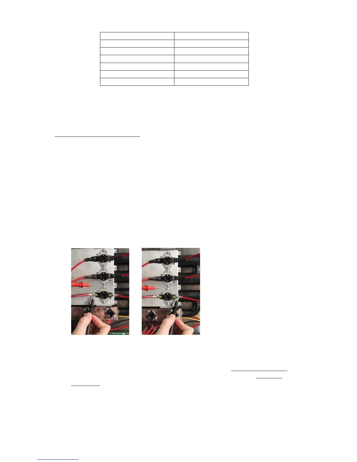
terminal block. Perform this step on the left-hand connection of each hi-limit
thermostat then again on the right-hand connection of each hi-limit thermostat.
3. If there is no voltage at the bottom of any hi-limit thermostat, then check the wiring
and connections between that hi-limit thermostat and the power distribution block.
4. If correct voltage is present at the bottom of the hi-limit thermostat but no voltage is
present at the top of the thermostat, then that hi-limit thermostat needs to be replaced.
5. If correct voltage is present on the top and bottom continue to Check the Thermistor
.
6. For three-phase units, if the magnetic contactor is pulled in, continue to Check the
Thermistor. Otherwise, starting at the left-hand connection of the lowest hi-limit
thermostat, check the voltage between the metal connection point of the thermostat
and the metal plate.
7. A voltage reading around 120V should be indicated. If no voltage is present at this
point, check the wiring and connections to this hi-limit thermostat from the magnetic
contactor or transformer, as applicable.
 Loading...