11
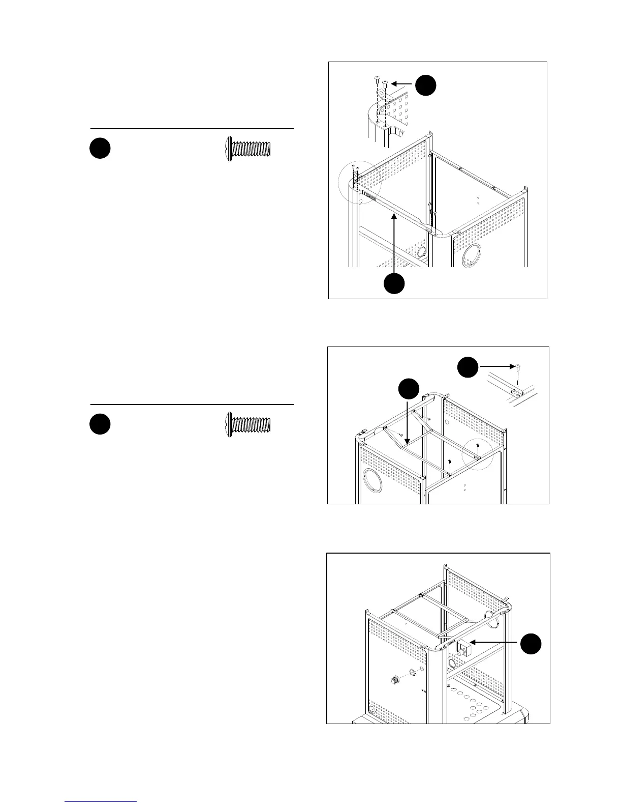
5. Attach the front beam (K) to the left panel and the right
panel with 2 screws (AA) on each side as shown.
6. Attach the drip tray support (L) to the front beam and rear
panel with 4 screws (AA) as shown.
7. Remove the cap and the nut from the igniter (I). Secure the
igniter to the left panel with the nut. Then, reassemble the
cap to the igniter.
Hardware Used
3/16-24 x 1/2 in.
Screw
X 4
AA
Hardware Used
3/16-24 x 1/2 in.
Screw
X 4
AA
AA
K
5
AA
L
6
I
7