S
Scott ReynoldsAug 3, 2025
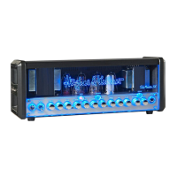
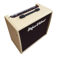
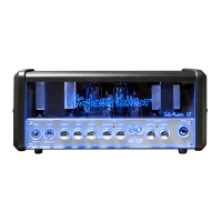
What to do if my Hughes & Kettner SWITCHBLADE TSC Combo 50 Amplifier has no sound?
- SStephen GoodAug 4, 2025
If your Hughes & Kettner SWITCHBLADE TSC Amplifier isn't producing any sound, there are several potential causes. First, check if the guitar's volume knob is turned up. Then, ensure the amplifier is switched from STANDBY to ON, and that the amp’s MASTER knob is also turned up. If you're using the effects loop, and it's set to SERIAL, make sure an effect device is connected. Also, check both the anode fuse and the tube heating fuse (tubes should glow) and replace them with fuses of the same rating if blown.