2
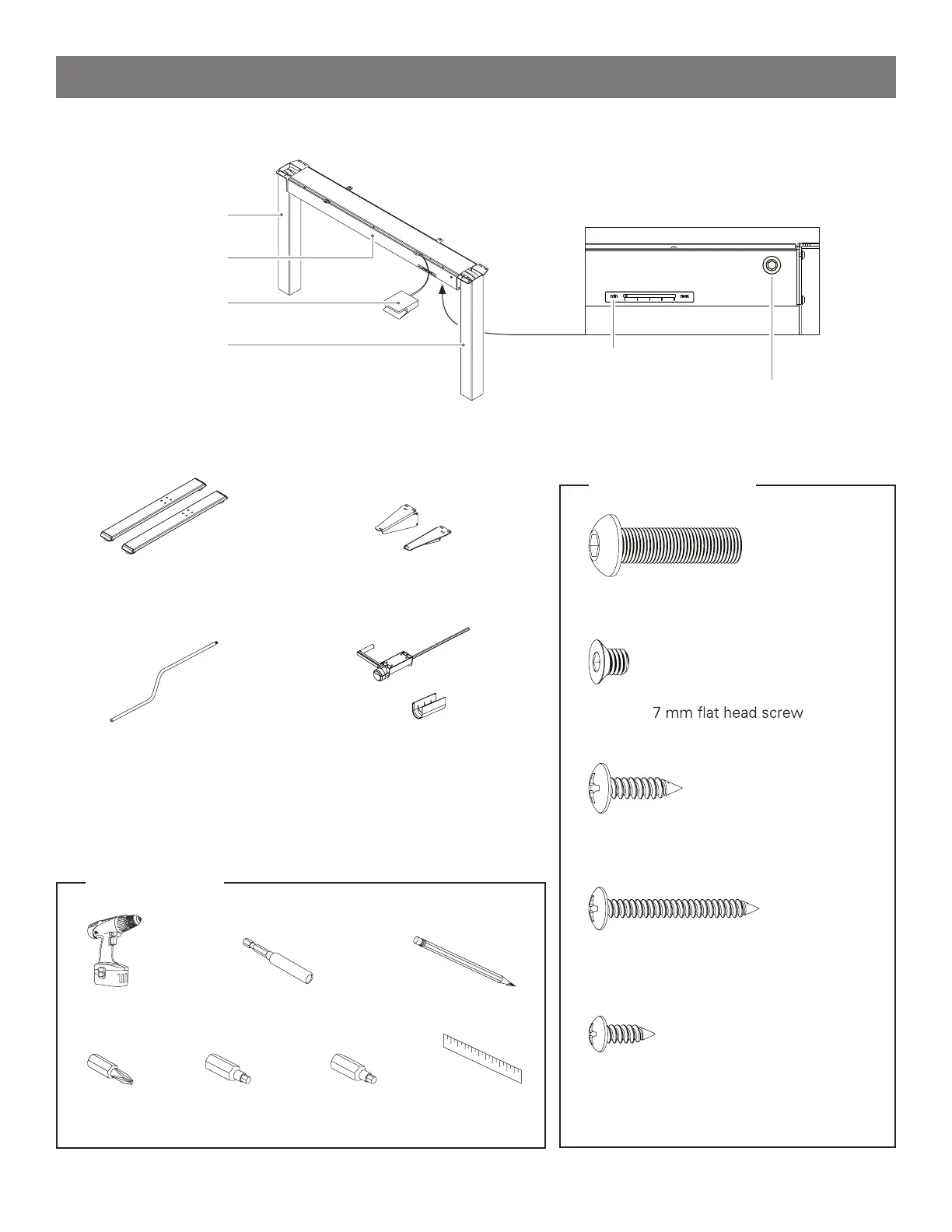
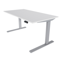
Base Assembly ( Front view)
Left leg
Cross-beam
Release paddle
Right leg
Tension Indicator window
Tension Adjustment screw
(2) Feet (2) Wing Brackets
Tension Adjuster Handle Mounted Tension Adjuster Handle
optional accessory
Tools Required
Power Drill/Driver Extension Hex Driver
#2 Phillips Bit 4 mm Hex Bit 5 mm Hex Bit
Hardware Included
(8) M8 × 30 mm button head screw
(12) No. 10 × ¾” pan-head wood screw
(4) No. 8 × 1½” pan-head wood screw
(4) M6 ×
(4) No. 8 × ½” pan-head wood screw
part of Mounted Tension Adjuster
optional accessory
*Work-surface not shown
Pencil
Ruler
Parts List