3
Attach the Feet
a. Turn the Base upside down so the Legs are pointing up.
b. Position the foot over the leg. Align the 4 holes in the
foot with those in the end of the leg. The longer portion
of the Foot should extend towards the front. (Fig. A)
c. Use the 5 mm hex driver, to install the (4) M8 × 30 mm
button head screws that secure the Foot to the Leg.
d. Repeat steps 1b– 1c for the second Foot.
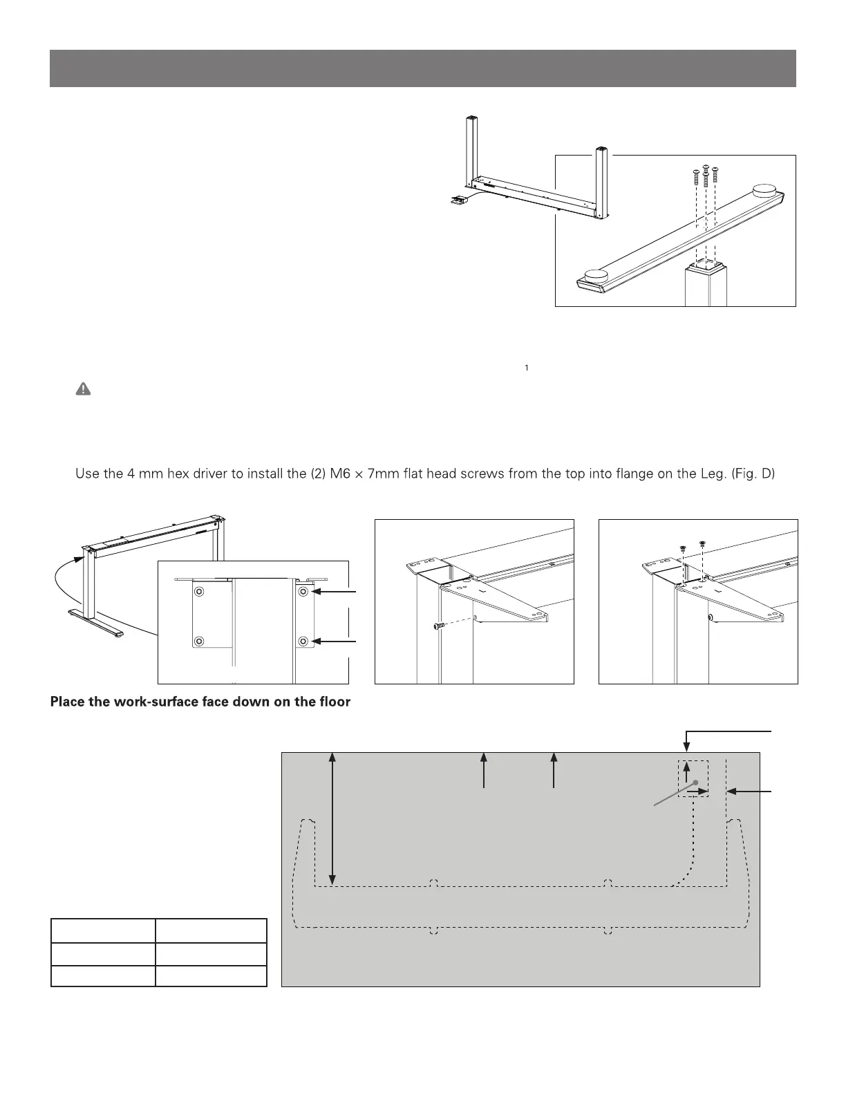
Attach the Wing Brackets
a. Turn the Base over so that it rests on it’s feet.
b. Starting on the Left, locate the 4 screws on the outside end of the cross-beam where it connects to the leg (Fig. B)
c. Use the 4 mm hex driver to loosen the upper-front screw, until there is a /8”(3 mm) gap under the screw’s head.
Caution: Do not fully remove this screw from the cross-beam or it can cause internal misalignment.
d. Use the 4 mm hex driver to completely remove the lower-front screw, set it aside.
e. Position the Left Wing Bracket (stamped L) on the end of the cross-beam, extending forward.
f. Replace the lower screw through the bracket into the cross-beam. Tighten both upper and lower screws. (Fig. C)
g.
h. Repeat Steps 2c– 2f for the Right side and Right side bracket.
Lay a soft material beneath it to avoid scratches.
The work-surface must measure
at least 3/4” (19 mm) thick.
1
2
3
Front
d
work-surface size d
30” (800 mm) 16 ½” (420 mm)
24” (600 mm) 13 ½” (350 mm)
Fig. M – Non Humanscale work-surface diagram.
2 ¼”
(60 mm)
1”
(25 mm)
Release Paddle
positioning
Fig. A – attaching the foot.
Fig. B
Fig. C Fig. D
remove
Left side shown
loosen
Assembly Instructions