Do you have a question about the Humminbird HDR 610 and is the answer not in the manual?
Select an appropriate mounting location for the HDR 610, considering visibility and support.
Drill a 2 1/8" diameter hole for the HDR 610 unit after selecting the mounting location.
Select and attach bezels and overlays, then assemble the unit for installation.
Insert the HDR 610 into the mounting hole and secure it with the 'U' bracket and wingnut.
Secure the buzzer to a metal bracket or wire bundle using the provided cable ties.
Connect the transducer cable to the keyed connector on the HDR 610 unit.
Connect the unit to a 12 VDC power source, using a fuse for protection.
Find a turbulence-free location on the transom for optimal transducer performance.
Mark and drill two mounting holes on the transom using the bracket as a guide.
Assemble the transducer and pivot arm, then mount it loosely for adjustment.
Route the transducer cable to the control head area, avoiding interference.
Connect the transducer cable to the correct terminal slot on the control head.
Perform a final test to confirm operation and adjust transducer angle.
Secure the transducer assembly to prevent it from kicking up, if desired.
Find a suitable location inside the hull for mounting the transducer.
Perform a trial installation to test performance before permanent mounting.
Route the transducer cable from the transducer to the depthsounder.
Mount the transducer inside the hull using slow-cure epoxy.
Explore options for mounting transducers on trolling motors.
Find a suitable location inside the hull for mounting a puck transducer.
Perform a trial installation to test puck transducer performance before permanent mounting.
Route the puck transducer cable to the depthsounder.
Mount the puck transducer inside the hull using slow-cure epoxy.
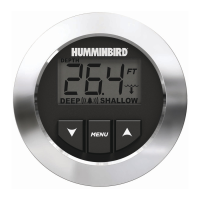
Understand the 7-segment display and keypad controls of the HDR 610 unit.
Learn how to use the SET, UP, and DOWN Arrow keys for various functions.
Configure the shallow depth alarm to alert when water is too shallow.
Configure the deep depth alarm to alert when water is too deep.
Select the desired units of measure (Feet, Meters, Fathoms) for readings.
Adjust depth readings based on transducer position relative to the keel or waterline.
Proper cleaning and maintenance procedures for the HDR 610 and transducer.
Guidance for resolving common operational problems and error conditions.
Instructions for USA customers on returning products directly to the factory for service.
Procedure for obtaining a Repair Authorization Number before sending the unit for service.
Customer support contact information via telephone, including hours of operation.
Customer support contact information via email, with typical response times.
The physical mailing address for direct shipping of products to Humminbird.
| Power Output | 500 Watts (RMS) |
|---|---|
| Voltage Range | 10-20 VDC |
| Frequency | 200 kHz |
| Depth Capability | 1500 ft |
| Water Resistance | Yes |