Do you have a question about the Humminbird HELIX 15 and is the answer not in the manual?
Lists necessary tools and hardware for installation.
Information on website resources, videos, and accessory guides.
Steps for selecting and preparing the control head mounting location.
Guidance on power cable length and recommended wire gauge.
Requirements for connecting to a 12 VDC power supply and appropriate fuse sizes.
Instructions for connecting the power cable to a fuse panel or directly to the battery.
Verifying accessory connections and GPS signal reception.
Performing a sonar test and powering down the unit.
Important safety warnings and cautionary notes regarding operation and repair.
Details on FCC regulations and environmental compliance (WEEE Directive).
Preliminary steps before transducer installation, including control head setup.
Overview of new and previously installed transducer scenarios.
Performing tests on the control head to verify transducer function and performance.
Securing the transducer mounting and drilling the final hole.
The Humminbird HELIX Series Control Head is a sophisticated marine electronics device designed to enhance your boating experience through advanced sonar and navigation capabilities. This installation guide outlines the process of gimbal mounting the control head and installing a transom transducer, ensuring optimal performance and longevity of your system.
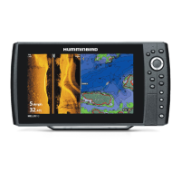
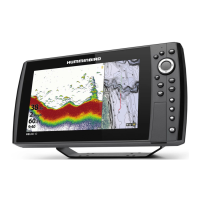
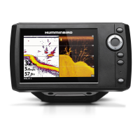
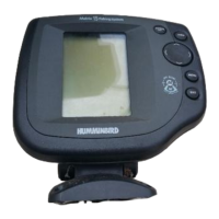
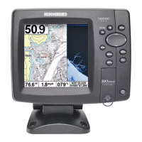
The HELIX Series Control Head serves as the central interface for your marine electronics system, displaying sonar readings, navigation data, and other accessory information. When connected to a compatible transducer, it provides detailed underwater views, helping you locate fish, identify underwater structures, and navigate safely. The system supports various sonar technologies, including traditional 2D sonar, Down Imaging®, and Side Imaging®, offering comprehensive underwater awareness. It also integrates with GPS for precise positioning and navigation, allowing you to mark waypoints, create routes, and track your movement on the water.
The control head is designed for ease of use with a clear display and intuitive controls. It features a POWER key to turn the unit on and off, and a MENU key to access various settings and views. Cursor keys (UP, DOWN, LEFT, RIGHT) allow for navigation through menus and selection of options. The VIEW key provides access to different display views, such as Sonar View, Accessory Test View, and GPS Diagnostic View.
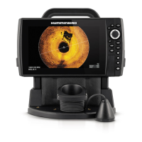
The control head is designed for gimbal mounting, allowing for flexible adjustment of the viewing angle. It comes with gimbal knobs and a bracket that enable you to secure the control head in a stable position while also allowing it to pivot through its full tilt range. This adjustability ensures optimal visibility during operation, regardless of your position on the boat. The bracket can be flipped for overhead mounting if preferred, with the opening in the bracket arms facing the rear of the control head.
A key feature of the HELIX system is its integrated cable tray, which plays a crucial role in securing and protecting the cables from potential damage. The cable tray is designed with specific slots for each connector (transducer, power, Ethernet, NMEA 2000, and COM communications), ensuring proper placement and preventing accidental disconnections. The tray also helps organize the cables, keeping them neat and untangled. Once the cables are routed through the tray and connected to the control head, the tray clasps securely into place, providing a robust connection.
The control head requires a 12 VDC power supply. The system includes a 6-foot (2-meter) power cable, which can be extended if needed using appropriate wire gauges to maintain optimal performance. It is crucial to connect the power cable to the electrical system of the boat via a fuse panel or directly to the battery, using the recommended fuse size and type (slow-blow or MDL equivalent) for your specific HELIX model. This protects the control head from power surges and ensures stable operation.
The transom mount transducer installation allows for fine-tuning of both the running angle and depth after mounting, which is essential for achieving the best sonar results. The transducer must be mounted in an area free of turbulent water, typically away from ribs, strakes, rivets, and propellers. For optimal performance, it should be positioned at least 15 inches (38.1 cm) to the side of the propeller(s) on outboard or inboard/outboard boats. The transducer must be mounted parallel to the waterline and fully submerged during operation to ensure a clear sonar signal. For Side Imaging® transducers, it is critical that nothing obstructs the side-looking beams.
The system allows for adjustments to the transducer's vertical and horizontal angles to optimize sonar performance. The transducer has a natural downward slant, which can be adjusted to be parallel to the water for Down Imaging® transducers. Testing the system at various boat speeds is crucial to identify and correct any issues with bottom readings. Incremental adjustments to the transducer's height and running angle are often necessary to achieve consistent high-speed performance.
The HELIX Series Control Head supports various accessories and Ethernet equipment, which can be purchased separately. The system automatically detects the transducer included with your control head. If a compatible accessory transducer is connected, you can set the transducer type on the control head, which will then add the related views and menus to the system, expanding its capabilities.
The cable tray not only organizes cables but also protects them from potential damage due to movement or environmental factors. It is important to ensure that cables are routed away from areas where they could be pinched, cut, or submerged in water. If cables are installed in splash-prone areas, applying dielectric grease to the inside of the connectors can help prevent corrosion.
Proper cable routing is essential to minimize electronic interference. Cables should be routed as far as possible from VHF radio antenna cables or tachometer cables. If there is excess cable, it should be gathered into a single loop or coil and stored in a protected location, as this method can reduce electronic interference.
Humminbird is committed to environmental responsibility. The products are designed to comply with the WEEE Directive, which requires the responsible management of waste from electronic products. This means that at the end of its life cycle, the product should not be disposed of with household refuse but should be collected for recycling and recovery of waste EEE.
The installation guide provides notes and cautions to help prevent common issues during installation. For example, it advises against using a high-speed driver for fasteners and emphasizes hand-tightening to prevent damage. In case of issues, the guide directs users to the Humminbird Web site for additional information, resources, and instructional videos. For complex issues or if extension cables are needed, Humminbird Technical Support is available for assistance. The control head operations manual, available for download, provides further configuration and operational details.
The use of marine-grade silicone sealant for drilled holes is recommended to prevent water intrusion and protect the boat's transom. Ensuring that mounting screws are snug but not overtightened during initial adjustments allows for flexibility, while final hand-tightening secures the assembly for long-term use. The robust design of the gimbal bracket and cable tray contributes to the overall durability of the system in harsh marine environments.
| Chartplotting | Yes |
|---|---|
| LakeMaster Compatibility | Yes |
| Navionics Compatibility | Yes |
| i-Pilot Link Compatibility | Yes |
| Radar Compatibility | Yes |
| NMEA0183 | Yes |
| NMEA2000 | Yes |
| Ethernet Port | Yes |
| Transducer | Included |
| Waterproof Rating | IPX7 |
| Display Pixel Matrix | 1280 x 800 |
| Sonar Type | CHIRP, Side Imaging, Down Imaging |
| Target Separation | 2.5 inches |
| Maximum Depth | 1500 feet |
| Temperature | Built-In |
| Backlight | LED |
| Power Input | 10-20V DC |
| GPS | Internal |
| Humminbird Basemap | Yes |
| Card Reader | SD card slot |
| Networking | Ethernet |
| Depth Capability | Up to 1500 feet |