J
Jamie CrawfordJul 29, 2025
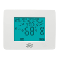
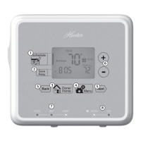
Why program does not change at my desired setting on Hunter 44459?
- MMark MccallJul 29, 2025
If the program on your Hunter Thermostat isn't changing at the desired setting, consider these possible causes: * The time may not be set properly to “AM” or “PM.” * The thermostat might be in “HOLD” or “Home Today” modes. * The day setting may be incorrect.