41343-01 7/1/2002
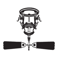
Bare or Green
Green
Approved
Connectors
Power
Wires
In
Ceiling
White
White
Black
Black/White
1
2
Connections:
Black
Wall Switch Wire For
Separate Control of Light Fixture
Ceiling
Plate
Outlet Box
2 x 4 Brace
Green Ground
Wire from Hanger
Pipe (not present
with flush mounting
option)
3 Wires
From Fan
(Note: Wall switch
must be acceptable
as a general-use
switch.)
Connect Blk/Wht Wire from fan
to Wall Switch Wire for separate
control of light fixture, or
Connect Blk/Wht Wire from fan
to Ceiling Black Wire if there
is no separate Wall Switch Wire
for the light fixture.
1
2
4. Connect the wires as shown in Fig-
ure 4c. To connect the wires, twist
the bare metal leads together.
Place a wire nut over the inter-
twined length of wire and twist
clockwise until tight as shown.
CAUTION
Be sure no bare wire or wire
strands are visible after mak-
ing connections.
5. Separate the connected wires by
placing the green and white wires
on one side of the outlet box and
the black and the black/white
wires on the other side of the
outlet box.
6. Turn the connectors upward. Push
the wires gently into the outlet
box.
Figure 4c - Wiring Diagram