unter 31 • AC Electric S
stems
.4
O NOT allow the dockside
ower cord to come in
ontact w
t
t
e water.
ever operate an
power
ool or other electrical equipment while
ou or the
evices are in contact with the water, as this ma
ause e
ectrocut
on resu
t
n
n s
oc
or
eat
.1.3 Isolation Transforme
Be
ond the shore power connection and the shore
power breaker,
our A
power will be routed throu
h the
Isolation Transformer. See the Mechanical Arran
ement
Illustration
or the location o
the I
Trans
ormer
The IS
Transformer is a standard “dr
” t
pe 3.6 KVA
trans
ormer that basicall
isolates
our boat
rom the
shore power. It is a valuable sa
et
eature aboard
our
t.
.1.4 AC Distribution Pane
The distribution panels
or both A
and D
power are
l
t
hin
th
n
v
t
ti
n
t
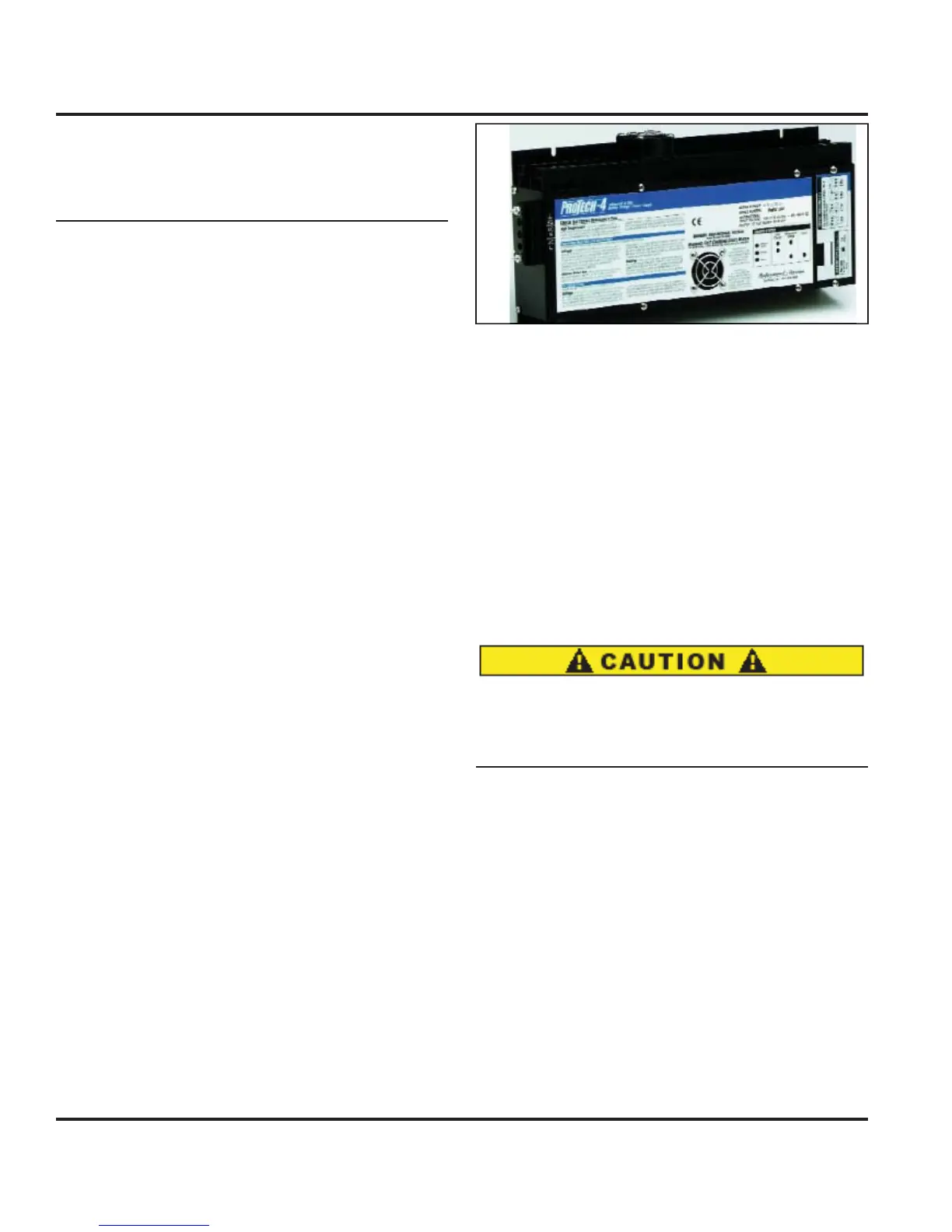
.1.5 Batter
Char
e
The boat
s batteries are normall
char
ed whenever the
n
ines are runnin
. I
ou are docked
or an extended
period o
time, operatin
D
devices and equipment will
drain the
ower from the batteries. Unless the batteries
are kept char
ed, the
ma
not have enou
h power to
start the en
ine when
ou need them
The batter
char
er
Fi
. 8.6
will automaticall
char
e
the en
ine batteries when the power suppl
is throu
h
the AC s
stem. The batter
char
er breaker is at the AC
i
tri
ti
n P
n
l
Leavin
the batter
char
er on whenever AC power is
available is a
ood idea. It will keep the batteries
ull
har
ed. A
ter the batteries are rechar
ed, it provides
a ma
ntenance or tr
c
e c
ar
e as nee
e
.
e
atter
har
er is under the chart table. Re
er to the manu
ac-
ture’s owner’s manual
or operatin
procedures.
.1.5.1 Basic Batter
Char
er Operation Procedur
1. Connect shore power cable to power AC Panel and
turn on the A
Main breaker.
2. Turn
Batter
har
er” breaker to the
N” position.
t
:
t
s not necessar
t
t
rn
n th
“H
t
rt”
batter
switch to provide char
in
power to the batter-
i
.
Fi
ure 8.5
The circuit breakers
or the batter
char
ers are located
n the A
Distribution Panel.
.1.6 En
ine Alternator Operation
1. Check sea strainer and open en
ine raw water sea-
k.
2. Turn batter
selector switch to the
1 position.
. Start en
ine.
Follow startin
instructions in the
En
ine Manual”
4. Turn batter
selector switch to both to char
e all bat-
t
r
.1.7 Water Heater
Be certain the water heater is full of water and does
not contain air. If the water heater is not full of wa-
ter, dama
e to the heatin
elements ma
result when
ectr
ca
ower
s turne
on to t
e un
t
Th
w
t
r h
t
r
n
n
ti
n i
ri
in th
Water S
stems Section
The water heater is powered b
the A
Distribution
n
.
t
m
t
m
n
tr
w
t
r
t
r
n
our home except in this case, the heater uses
volt
220 overseas
, but it uses elements to heat the water
to a specified temperature. Consult the manufacturer’s
documentation
or an
internal in
ormation about the
w
t
r h
t
r.
.1.
Microwav
The microwave is powered with the 120 volt
220 over-
seas
power throu
h the breaker marked “Microwave.”
There is a 120 volt
220 overseas
receptacle behind the
microwave that it is plu
ed into. This outlet is not part
f the GFI circuit. It is protected b
the breaker on the