Hunter 31
8.9
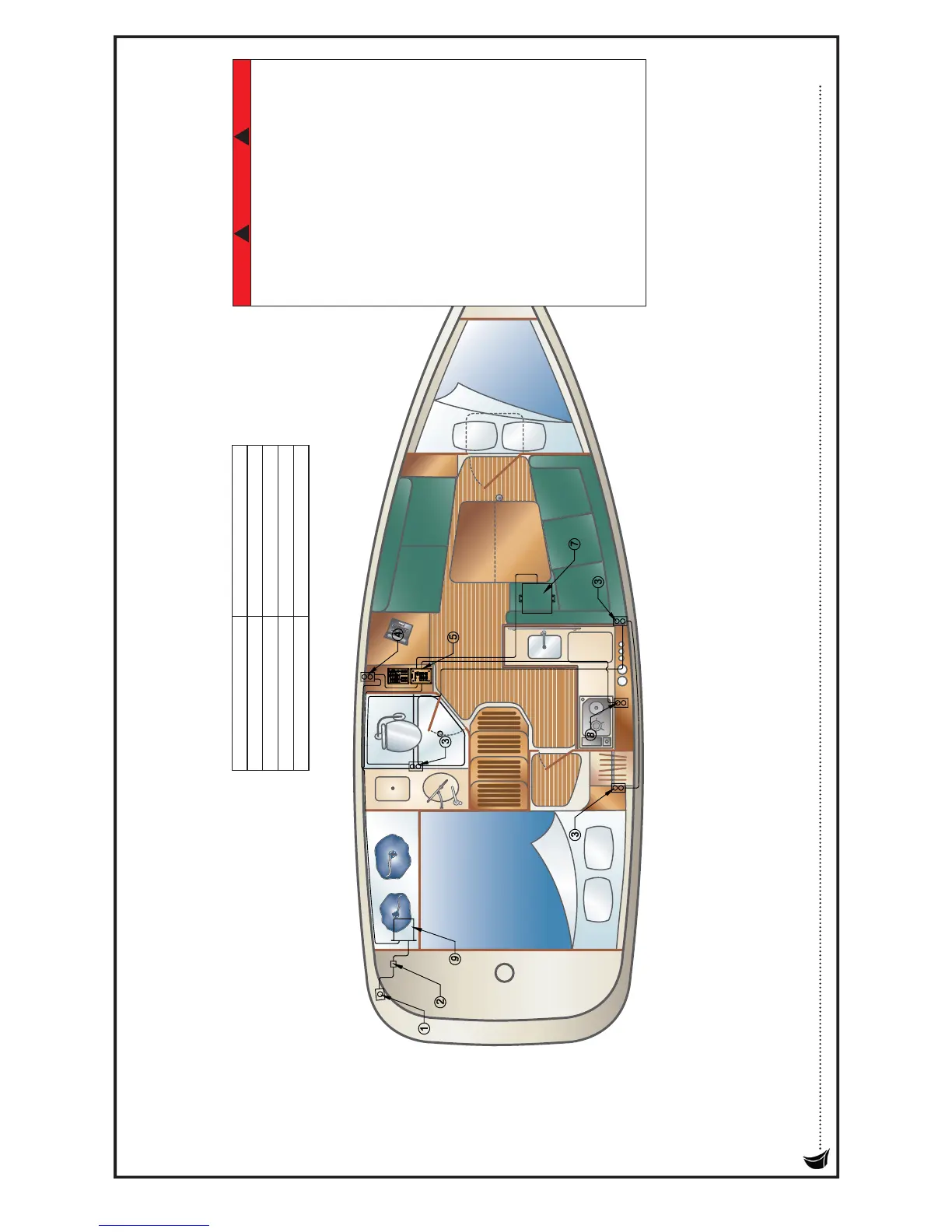
AC Electric Wire Run Diagram
1. SHORE POWER INLET 6. DC PANEL
2. SHORE POWER BREAKER 7. WATER HEATER
3. AC OUTLET 8. MICROWAVE (OPTIONAL)
4. GFCI OUTLETS 9. ISOLATOR TRANSFORMER
5. AC PANEL
NOTE: VANITY HEAD OUTLET NOT
SUPPLIED IN SOME COUNTRIES.
Alterations or extensions to the electrical
system can cause electrical shock or fire.
Only trained, competent, and certified
electricians should perform any electrical
maintenance, work, or changes to your
boats electrical system.
Always run the blowers for at least
four minutes before starting any engines.
Internal combustion engines produce
carbon monoxide, a dangerous,
poisonous gas. Be sure and
read the boating safety chapter
concerning Carbon Monoxide before
starting any engines.
Never work on an energized circuit,
Always treat any circuit as if it were live!
Electricity cannot be detected without
specialized test equipment.Never think
you know whether a circuit is "live",
always have qualified, competent
professionals inspect or make repairs to
your electrical systems.
DA NG E R
! !