nt
r
• D
Electric
7.
7.3.4.1 Basic Refri
erator Operation
1.
n standard batter
char
er model, turn on house
batter
selector switch
under chart table
.
2. Turn on Main D
breaker at Batter
wtich Panel.
. Set Thermostats to desired tem
erature.
Note: I
leavin
unit on when awa
rom boat be sure
s
ore power ca
es are connecte
an
atter
c
ar-
er is on to prevent batter
drain.
ptional inverter
quipped models char
e circuit is automatic i
shore
ower
s connecte
an
as
ower to
a
n
str
ut
on
anel
.
Note: Consult product manual for operatin
the refri
-
r
t
r
n
th
r in
rm
ti
n
n th
nit.
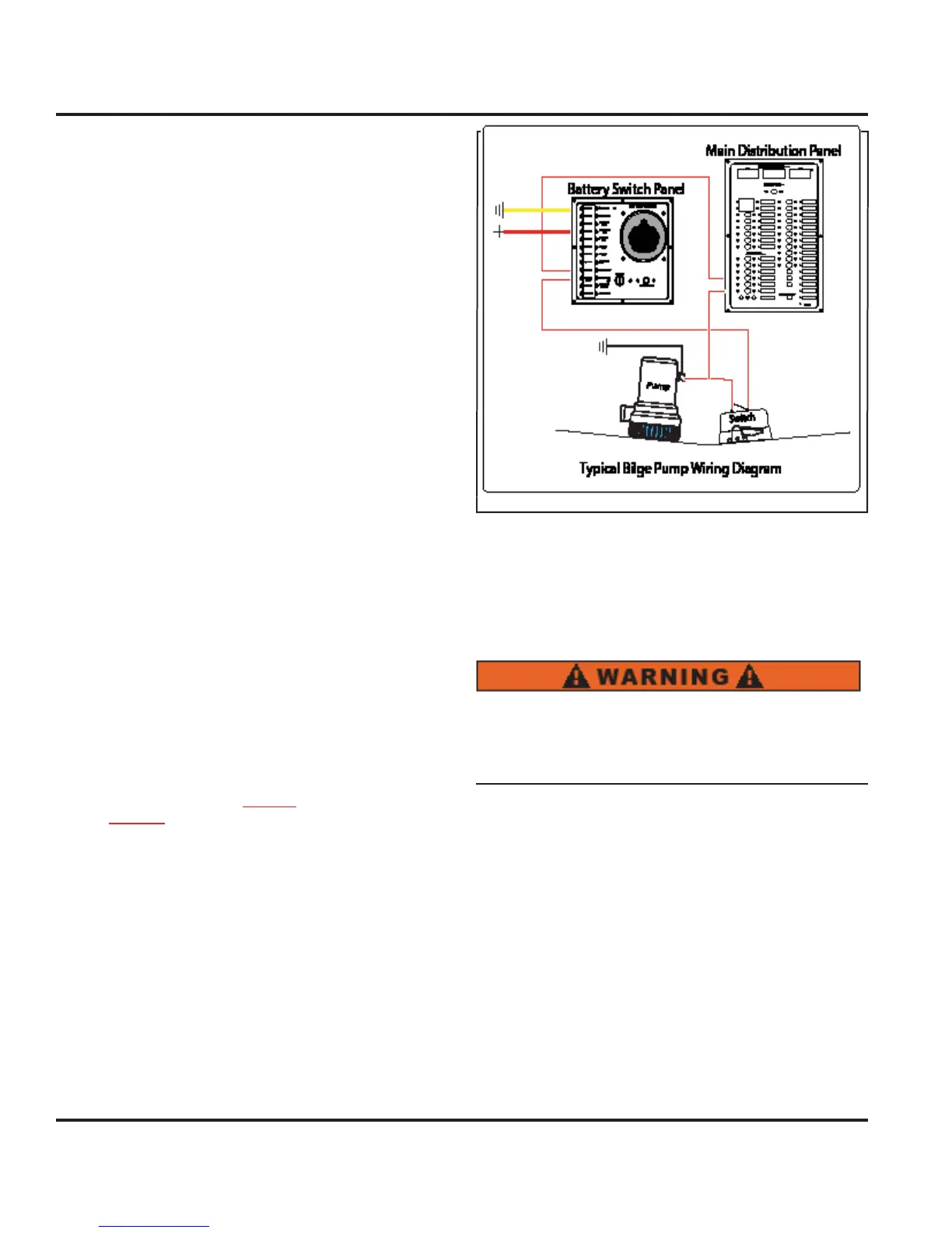
7.3.5 Bil
e Pump S
stems
Your boat is equipped with 1 main bil
e pump and
1
ptional
emer
enc
bil
e pump. For locations
the bil
e pump s
stems, consult
our Mechanical
Arran
ement Drawin
or the
anitar
stems Drawin
The Bil
e Pump
stem consists o
a pump and a
loat
switch. When the water level rises
ar enou
h to activate
the float switch, this activates the pump which lowers the
water level down to a point that the
loat switch stops the
power. Fi
. 7.4 shows
ou the t
pical wirin
For more information about
our bilge pump s
stem, see
anitar
stems
7.3.5.1 To manuall
operate
our bil
e pumps
Note: The power to the MDP does not need to be energized in
order to manually operate your bilge pumps.
1. Locate the bil
e pump switches at the Nav station and
sw
tc
t
em to t
e manua
pos
t
on
2. Another procedure to be used in extreme circumstanc-
s involves locatin
the float switch and manuall
rotatin
th
l
t h
n
l
n th
i
th
l
t
wit
h t
im
l
t
the
loat switch bein
underwater. This will ener
ize the
pump an
t
e pump w
operate.
7.3.6 Shower Sum
The shower sump is part o
the
anitar
stem and
more information about the Shower Sum
can be found
in that section. However, the reset
or the
hower
ump
an be
ound on the 12 Volt D
Panel.
Fuel fumes in the en
ine compartment can explode.
Before workin
on electrical wirin
, ventilate
en
ine room and disconnect batter
cables to
revent s
ar
s.
7.3.7 Ventilation
entilation is a ver
important issue with
our boat, with
the potential
or
arbon Monoxide buildup
ee Boatin
afet
Section
, alon
with the simple comfort of fresh
air or air conditionin
, ventilation is a standard that is a
necessit
n
our boat, there are essentiall
three t
pes o
ventila-
tion, the air conditionin
s
stem
A
s
stem
, the blower,
and the Bomar hatches, which suppl
ou with fresh
air when opened.
ince the air conditionin
s
stem is
A
powered
see A
Electric
ection
and the hatches
require no power, we will detail the blower
or fans
, and
their
unction, here.
or
ower
ocat
on, consu
t
our
ec
an
ca
rran
ement