nt
r
• D
Electric
7.
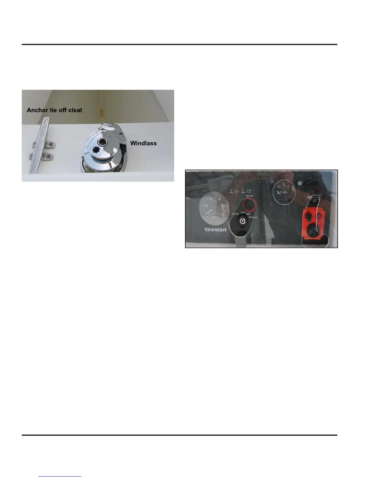
Note: If windlass becomes inoperable electricall
, a
manua
w
nc
an
e
s su
e
For more in
ormation about
our windlass, re
er to
our
wn
r
m
n
l.
Fi
ure 7.5
7.3.12 Instruments
The breaker marked “Instruments”, on the 12 Volt DC
anel supplies power to the instruments on
our boat.
For more in
ormation about the controls o
our instru-
ments consult product manual in
our owner
s packet
7.3.13 GP
The breaker marked
P
”, on the 12 Volt D
Panel
supplies power to the
P
on
our boat. For more in
or-
mation about the controls of
our instruments consult
product manual in
our owner
s packet
7.3.14 TV/DV
The reset marked
TV
DVD”, on the 12 Volt D
Panel
supplies power to the TV/DVD on
our boat. For more
in
ormation about the controls o
our instruments con-
sult product manual in
our owner’s packet.
7.3.15 Head
The reset marked
Head”, on the 12 Volt D
Panel sup-
plies power to the Head on
our boat. For more informa-
tion about the controls o
our instruments consult prod-
uct manual in
our owner’s packet
7.3.16 CO Monitors
For
our protection, we have installed C
monitors
aboard
our boat. Be sure and check
our
wner’s
acket
or more in
o concernin
our
detectors. You
an also review the dan
ers of C
in the Boatin
Safet
ha
ter of this manual.
o not spra
waxes or cleanin
a
ents on the monitor.
7.3.17 Fire Extin
uishin
S
stems
Option
In the en
ine room, there is a fire extin
uishin
bottle
installed. This s
stem is D
powered with a rela
, or
module”, and the alarm at the helm station.
When a
ire is detected on
our boat, the alarm will sound
and set o
the Halon bottle. This rela
will shut down
t
e en
ne, an
ower.
o reset t
e s
stem, act
vate
the override switch on the monitor at the helm.
ee Fi
.
7.
.
Fi
ure 7.
7.3.18 Maintenanc
The maintenance o
our D
s
stem is ensurin
that all
onnect
ons are c
ean, t
t, an
covere
w
t
a corros
on
inhibitor compound.
Fire Alarm
High Water Alarm