NOTE
For lockout / tagout instrucons, refer to ANSI Z244.1.
NOTE
Scratches to powder-coat should be touched up as soon as possible, on an as-needed basis.
Maintenance is to be performed by shop employee or trained li service personnel.
Worn, damaged or broken parts need replaced with parts approved by the original equipment manufacturer or with parts
meeng original manufacturer specicaons.
MAINTE-
NANCE
SCHED-
ULE
PERFORM THE FOLLOWING MAINTENANCE
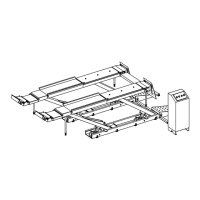
Daily Check that all safety warning labels are accessible and readable. Check for proper operaon of the li
controls. Check auxiliary locks at all four posts for free rotaon and ensure they properly line up with
lock ladder. Check the air lock at all four posts for free movement and ensure they are properly lined
up with the lock ladder. KEEP LOCK AREA CLEAN AND FREE OF DEBRIS AT ALL TIMES. Check the
hydraulic cylinder, power unit, hydraulic lines and ngs, air lines and ngs, and air cylinders for
leaks. Any leak must be repaired immediately. Check the oor near the base of each post for cracks or
loose concrete around the lag bolts. If any aws are found, stop using the li immediately. This is an
indicaon of an unsafe condion and the concrete will have to be replaced. Check for unusual noises,
sudden movements, errac operaon or evidence of chips or lings during use. Check all four liing
wire ropes for damage or wear. If any signs of severe corrosion, broken or damaged strands, wire rope
elongaon, reduced cable diameter, or any other changes in appearance as compared to a normal wire
rope are found, the li must be taken out of service and the wire rope(s) must be replaced prior to
further use. Fully lower the li and check the poron of the wire ropes running vercally inside each
post. Pay close aenon to the poron of the wire rope that enters the threaded stud at the top of
each post. Broken strands indicate signs of fague and if found the wire rope(s) must be replaced prior
to further use. Raise the runway just enough for observaon and set on the mechanical locks. Inspect
the wire ropes by looking through cutouts in the boom of the runways. Note: Use a trouble light
for better visibility. Raise the runways to several intermediate locaons and set on the mechanical
locks. Inspect the wire ropes by looking through cutouts in the boom of the runways, and inside the
inspecon door on the rear beam. Note: Use a trouble light for better visibility. Fully raise the runways
and set on mechanical locks. Inspect the wire ropes by looking through cutouts in the boom of the
runways, and inside the inspecon door inside the rear beam. Note: Use a trouble light for better
visibility. Check all sheaves for wear or damage. Look for cracks, worn surfaces, or abnormal play or
looseness as they rotate around mounng shas. Check that all sheave mounng sha retaining bolts
are ght. Check for any uid loss from the hydraulic system. NOTE: When adding hydraulic uid, the lift
MUST be lowered completely. Hose down with water and blow dry with compressed air when salt, ice,
snow or other corrosive condions exist.
Weekly Check the turning angle gauges and rear slip plates for smooth and easy operaon. Clean by blowing
out with clean, dry compressed air. Disassembly is not required. DO NOT lubricate turning angle plates
or slip plates. (CAUTION: Always wear eye protection when using compressed air). Check anchor bolts
on each post for ghtness. Torque to 100-110 -lb. Check and lubricate rear ramp pivots with SAE 30
oil.
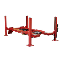
4-Post Lift Rack Models L451 & 454 Operations Manual
Page 25 of 28