This document is an operations manual for the Hunter Engineering Company's 4-Post Lift Rack Models L451 and 454. It provides comprehensive information regarding the safe operation, maintenance, and technical specifications of these automotive lift racks.
Function Description
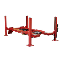
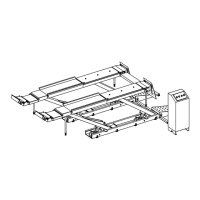
The Hunter 4-Post Lift Rack Models L451 and 454 are designed for automotive vehicles, allowing them to be driven onto the rack and lifted to a desired height. This elevation provides access to the underside of the vehicle for various services, including maintenance, repairs, and alignments. The lifts are intended for use in servicing and alignment of automotive vehicles.
Important Technical Specifications
The manual highlights several critical technical specifications, primarily concerning weight capacities and operational parameters:
- Maximum Weight Capacity: The lifts have varying maximum weight capacities depending on the model and specific components. For the main lift rack, the maximum weight capacity is 18,000 lbs (8,165 kg).
- Jack Capacity: For optional jacking beams, the capacities are specified:
- 4,500 lbs (2,041 kg)
- 6,000 lbs (2,722 kg)
- 8,000 lbs (3,629 kg)
- 9,000 lbs (4,082 kg)
It is crucial that the total lifted load for two jacks does not exceed the rated capacity of the lift.
- Air Supply: The maximum air supply required is 150 PSI (10.3 BAR).
- Duty Cycle: The lift has a duty cycle of 60 seconds ON and 540 seconds OFF for a 10-minute (600-second) cycle.
- Hydraulic Fluid: Hunter's specially filtered DEXRON III transmission fluid (part number 148-128-2) is specified for the hydraulic system. The system requires 4 gallons (15 liters) of this fluid, which should be filled when the lift is in its fully lowered position.
- Wire Rope Replacement: The complete wire rope set must be replaced every 20,000 cycles or every six years, whichever comes first, unless earlier replacement is indicated by inspections.
Usage Features
The manual details various usage features and operational instructions to ensure safe and efficient use of the lift racks:
- Controls: The L45x 4-post lifts feature consoles mounted to the front left post, housing controls for raising and lowering the lift.
- Raising the Lift: To raise the lift, the "RAISE" button is depressed and held until the desired height is reached. The pump operates during this process.
- Lowering the Lift: To lower the lift, the "RAISE" button is briefly pressed (usually one second) to lift the rack off the locks, then the "LOCK RELEASE" button is pressed and held simultaneously with the "LOWER" button until the desired height or ground level is reached. The lift should be set onto locks by pressing "LOWER" again.
- Mechanical Locks: The lift incorporates mechanical locks that engage automatically when lowering. Users are instructed to listen for the sound of these locks passing over their detents.
- Choking Procedure: Before operation, the vehicle's brake must be set, and a rear wheel must be chocked. Turning angle gauges should be adjusted to match the vehicle's tread width.
- Workstep (Optional): Portable worksteps can be used for access. They must be fully engaged and locked into the cutouts on the side of the runway. Yellow decals indicate if the workstep is not properly locked.
- PowerSlide Slip Plates (Optional): For models with PowerSlide, slip plates automatically lock when the lift is lowered to the floor. Controls for unlocking and locking these plates are located near the lift controls or on the FIA console. An "Unlock" indicator glows when unlocked.
- Inflation Station (Optional): This feature allows for tire pressure adjustment. Users connect air lines to the vehicle, set desired pressure using control arrows, and LED indicators (RED, YELLOW, GREEN) show the status of adjustment. The hose should be pulled gently and not past a red marked area, and retracted by pulling for a short stroke to prevent damage.
- Jacking the Vehicle: The manual describes how to pivot the jack from a stowed horizontal position to an upright, locked position. Pivot lock pins must be fully engaged, indicated by a "LOCKED" position on the indicator. It is explicitly warned not to operate the lift with jacks in use.
Maintenance Features
The manual provides a comprehensive maintenance schedule to ensure the longevity and safe operation of the lift racks:
- Daily Maintenance:
- Check all safety warning labels for readability.
- Verify proper operation of lift controls.
- Inspect auxiliary locks and air locks at all four posts for free movement and proper alignment with the lock ladder. Keep the lock area clean.
- Check hydraulic cylinder, power unit, hydraulic lines and fittings, air lines and fittings, and air cylinders for leaks. Repair any leaks immediately.
- Inspect the floor near the base of each post for cracks or loose concrete.
- Check for unusual noises, sudden movements, erratic operation, or evidence of chips/filings.
- Inspect all four lifting wire ropes for damage, wear, corrosion, broken strands, elongation, or reduced cable diameter. Replace immediately if any issues are found.
- Fully lower the lift and inspect the wire ropes running vertically inside each post, paying close attention to the threaded stud at the top.
- Raise the runways to intermediate locations and fully raise them, setting on mechanical locks, to inspect wire ropes through cutouts in the bottom of the runways and inside the inspection door on the rear beam, using a trouble light for better visibility.
- Check all sheaves for wear, damage, cracks, or abnormal play/looseness. Ensure sheave mounting shaft retaining bolts are tight.
- Check for fluid loss from the hydraulic system. Add hydraulic fluid only when the lift is fully lowered.
- Hose down with water and blow dry with compressed air when salt, ice, snow, or other corrosive conditions are present.
- Weekly Maintenance:
- Check turning angle gauges and rear slip plates for smooth operation. Clean with compressed air (wearing eye protection). Do NOT lubricate turnplates or slip plates.
- Check anchor bolts on each post for tightness (torque to 100-110 ft-lb).
- Check and lubricate rear ramp pivots with SAE 30 oil.
- Monthly Maintenance:
- Check wire ropes for damage and lubricate with a thin oil (SAE 5W-30), avoiding used motor oils or solvent-based oils. Replace immediately if damage is found.
- Inspect the entire lift for loose, damaged, or broken bolts.
- Blow dirt from inside slide plates with compressed air (do not grease).
- Clean swing air jacks thoroughly with a degreasing solvent and dry. Wipe cylinder tubes with oil. Apply SAE 30 oil to rollers and pivot pins.
- Clean both rams and apply SAE 30 oil.
- Check proper operation of control levers and verify two-handed operation of raise/lower controls.
- Check for air leaks.
- Check that locks are fully engaging and unlocking.
- Check that pivot lock pins are undamaged and lock/unlock freely.
- Verify counter balance spring is functional.
- Perform a general structural check for damage, corrosion on columns and runways. Rinse immediately if corrosive agents contact the lift or wire ropes, and re-lubricate wire ropes.
- Check the power unit reservoir oil level. Add Hunter's specially filtered DEXRON III transmission fluid (148-128-2) if necessary, ensuring the lift is fully lowered.
- Apply SAE 30 oil to all pivot pins, ramp pins, wheel stop pins, and leg shafts.
- Wipe hoist cylinder with oily cloth and lubricate gear rack.
- Remove top slip plate, clean thoroughly, coat unpainted surfaces with paraffin, and replace any broken balls. Apply SAE 30 oil to jack linkage pins and levers.
- Every Six Months:
- Check runways and re-level as required.
- Apply SAE 70 grease to grease fittings on swing air jack cylinders with the jack fully extended (two shots sufficient).
- Annually:
- The entire lift should be inspected by a factory-authorized service representative.
- Apply 3 shots of Moly-Grease to each fitting on both sides of the jack channel assembly.
- Apply 1-2 shots of Moly-Grease to each fitting on both sides of the lower cylinder assembly with the jack fully extended. Composite cylinders without grease fittings do not require annual lubrication.
- Every Two Years:
- Change hydraulic fluid (4 gallons/15 liters of Hunter's specially filtered DEXRON III transmission fluid, 148-128-2). Drain fluid from the reservoir with the lift lowered completely and clean any metal particles from the magnet.
- Every Six Years:
- Hunter Engineering requires that the lifting cables on all 4-Post models be replaced by Hunter Service representatives.
Important Notes on Maintenance:
- Scratches to powder-coat should be touched up as soon as possible.
- Wire ropes are high-wear items and must be inspected regularly. Replacement is mandatory at the first sign of severe corrosion, broken strands, elongation, or reduced diameter.
- The best preventive maintenance against wire rope corrosion is consistent lubrication to prevent moisture ingress.
- Maintenance is to be performed by a shop employee or trained lift service personnel.
- Worn, damaged, or broken parts must be replaced with approved parts from the original equipment manufacturer or parts meeting original manufacturer specifications.
- The suggested maintenance schedule is for normal working conditions; unusually dirty or harsh corrosive conditions (e.g., heavy winter road salt) may require more frequent maintenance.
- If any unsafe conditions are observed, the lift must be taken out of service immediately and reported to a supervisor, employer, or owner. Repairs must be made by qualified automotive lift personnel before further use.