8
42650-01•07/30/07•HunterFanCompany
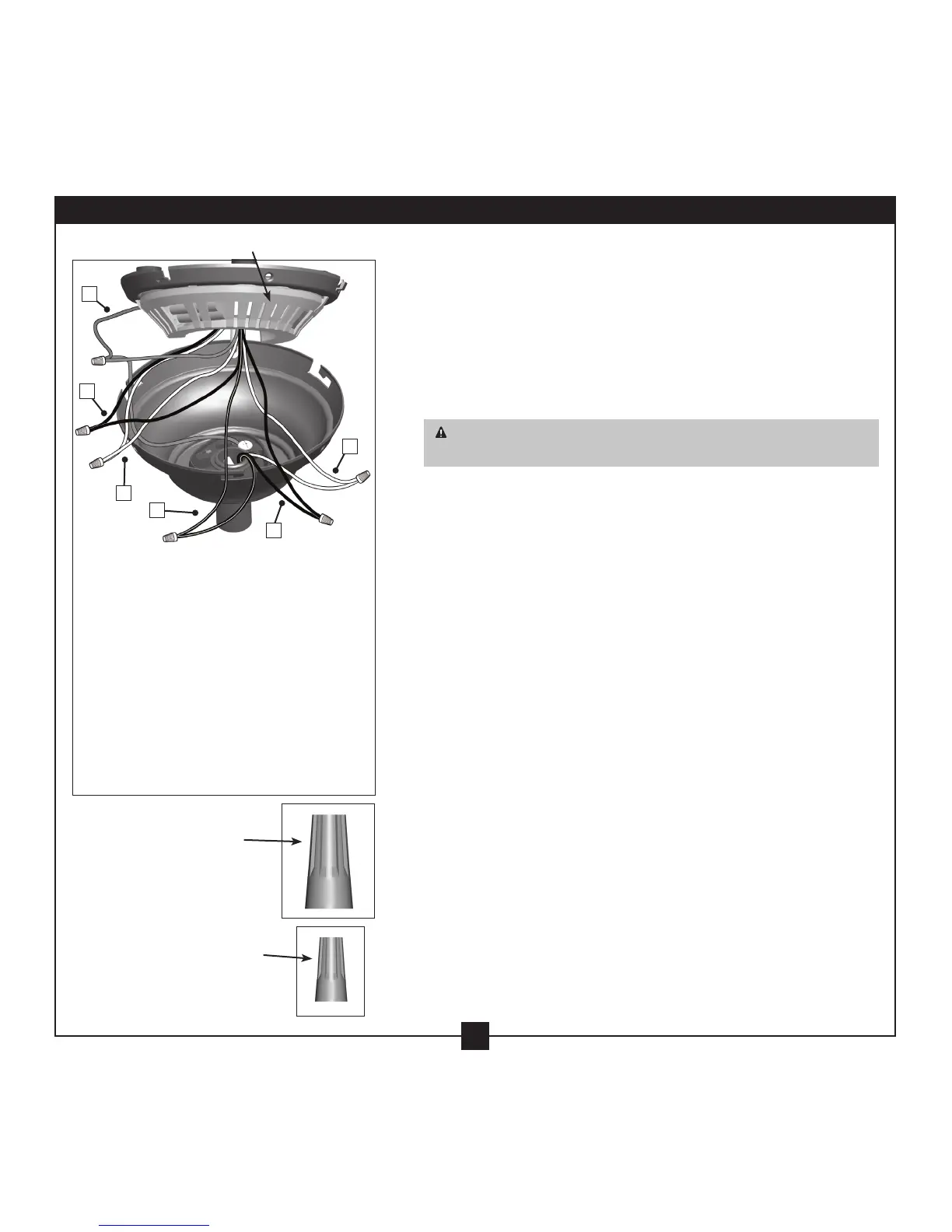
Step 5-3
A •Ground/Green
Step 5-4
B •CeilingBlack
•ReceiverBlack:“LIVEIN”
C •CeilingWhite
•ReceiverWhite:“NEUTRALIN”
Step 5-5
D •FanBlack/White
•ReceiverBlack/White:“LIGHTOUT”
E •FanBlack
•ReceiverBlack:“FAN”
F •ReceiverWhite:“LIGHTANDFANCOMMON”
•FanWhite
All wiring must be in accordance with national and local electrical
codes and ANSI/NFPA 70. If you are unfamiliar with wiring, use a
qualified electrician.
5-1. Make sure the power is still off.
5-2. To connect the wires, hold the bare metal leads together and place
a wire nut over them, then twist clockwise until tight. For all these
connections use the wire nuts provided.
CAUTION: Be sure no bare wire or wire strands are visible after
making connections.
5-3. Connectthegroundwirefromtheceilingtothegreenground
wire from the ceiling plate and the green ground wire from the
downrod or low profile washer.
5-4. Usingthelargewireconnector,connectthewhitewireandthe
black wire from the ceiling as follows:
•
e white (common) power wire from the ceiling to the white
wirefromthereceiver(markedonredtag“NEUTRALIN”)
•eblackpowerwirefromtheceilingtotheblackwirefrom
thereceiver(markedonredtag“LIVEIN”)
5-5.Usingthesmallwireconnector,connectthewiresfromthefanas
follows:
•eblackwirefromthefantotheblackwirefromthereceiver
(markedonwhitetag“FAN”)
•ewhitewirefromthefantothewhitewirefromthereceiver
(markedonwhitetag“LIGHTANDFANCOMMON”)
•eblack/whitewirefromthefantotheblack/whitewirefrom
thereceiver(markedonwhitetag“LIGHTOUT”)
5-6. Check each connection to make sure no bare wire or wire strands
are visible. Push all wires and wire nuts back through the ceiling
plate hole into the outlet box.
5-7. Runthewhiteantennawirefromthereceiverthroughoneofthe
slots in the ceiling plate so that it rests between the ceiling plate
and the ceiling. Push it to the edge of the ceiling plate for clear
reception.
Large Wire
Connector
Steps 5-3 – 5-7
Small Wire
Connector
Receiver
A
B
C
E
F
D
5 • Wiring the Fan