Wireless Rain-Clik
™
Rain Sensors
Installation Instructions
Hunter Industries Incorporated • The Irrigation Innovators
© 2003 Hunter Industries Incorporated
1940 Diamond Street • San Marcos, California 92069 • TEL: (1) 760-744-5240 • FAX: (1) 760-744-7461
www.HunterIndustries.com 23-461 8/03
Receiver Installation, Other Controllers (continued):
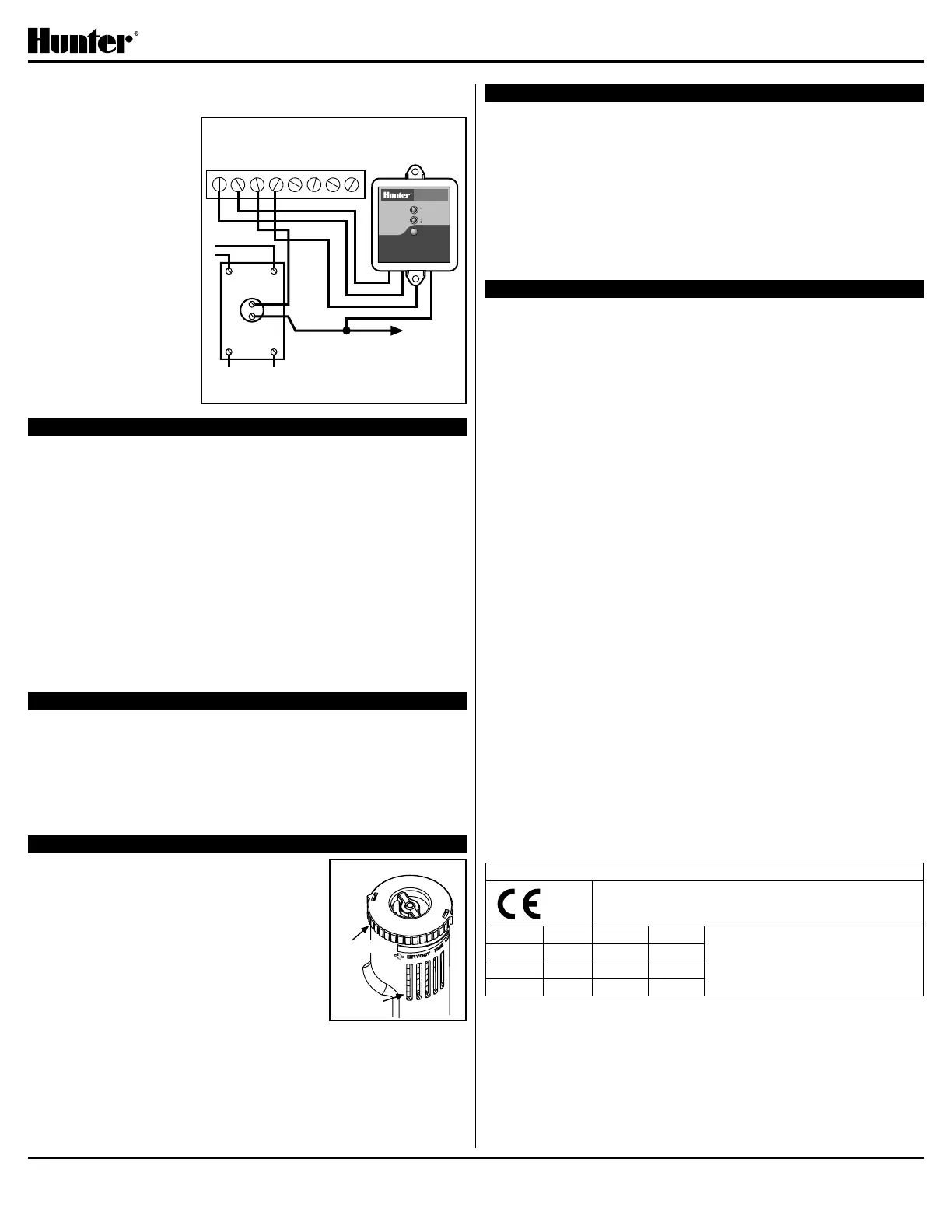
C. 24 Volt Solenoid Valves with Booster Pump (See Figure 5)
Locate the common wire
to the solenoid valves and
the common wire leading
to the coil of the relay that
starts the pump. If these
two wires are connected
to the “common” terminal
on the controller,
disconnect both of them.
Twist together these two
wires along with one wire
from the Rain-Clik™, and
secure with a wire nut.
Attach the other wire of
the Wireless Rain-Clik™
receiver to the “common”
terminal on the controller.
Note: The pump circuit
output must be 24 Volts
in this situation. Do not
proceed if 110V.
SETTING THE TRANSMITTER ADDRESS AT THE RECEIVER
Units purchased as a kit will already have their address learned.
No addressing is necessary, however if the receiver or transmitter is
replaced, you need to reset the address.
Each transmitter produced has a unique address hard-coded into it. A receiver
must learn this address to work with that transmitter. This step will only be
necessary if transmitters and receivers are purchased separately.
1. Prior to applying power (yellow wires) to the receiver, press and hold the
receivers pushbutton.
2. While the pushbutton is being held apply power to the receiver – the
receiver’s “sensor status” LED should light up yellow indicating the receiver
is ready to learn an address.
3. Push and hold the quick response post on the transmitter/sensor.
4. Within 4 seconds, the receiver’s “sensor status” LED should turn red.
5. Release the transmitter/sensor’s quick response post and within 4 seconds
the LED on the receiver should turn green. The address is now learned and
will be retained even in the event of a power outage.
OPERATION
Once the receiver and transmitter have been installed and the receiver has
learned the transmitter’s address, the system is ready to work. The receiver
has two LEDs, which indicate the state of the system. The STATUS LED will be
RED when the sensor is wet (watering disabled), and GREEN when the sensor
is dry (watering enabled). There is also a RED BYPASS LED on the receiver. If
this LED is lit, the rain sensor is bypassed and watering will always be allowed.
Even though the sensor is bypassed, the STATUS LED will continue to alert you
of the state of the sensor (Wet or Dry).
ADJUSTMENTS AND OPERATION
The Wireless Rain-Clik can keep the irrigation
system from starting or continuing after rainfall.
The time that it takes the Wireless Rain-Clik to
reset for normal sprinkler operation after the rain
has stopped is determined by weather conditions
(wind, sunlight, humidity, etc.). These conditions will
determine how fast the hydroscopic discs dry out,
and since the turf is also experiencing the same
conditions, their respective drying rates will roughly
parallel each other. So when the turf needs more
water, the Rain-Clik is already reset to allow the
sprinkler system to go at the next scheduled cycle.
There is an adjustment capability on the Wireless Rain-Clik that will slow down
the reset rate. By closing the “vent” (see Figure 6) to completely or partially
cover the ventilation slots, the hydroscopic discs will dry more slowly. This
adjustment can compensate for an “overly sunny” installation location, or
peculiar soil conditions. Experience will best determine the ideal vent setting.
BYPASSING THE SENSOR
The sensor may be bypassed by using the built in bypass feature in the SRC,
Pro-C or ICC. On other controllers the sensor may be bypassed by pressing
the “BYPASS” button on the receiver. The RED BYPASS LED on the receiver
will be lit when the sensor is bypassed. Pressing the “BYPASS” button again will
cause the RED BYPASS LED to go back out thus re-enabling the sensor.
Battery Life: The Wireless Rain-Clik transmitter is designed to work daily
for up to ten years with the original battery. The sealed unit is available as a
replacement part. Should you need to change the transmitter the receiver will
have to learn the new transmitter address.
There is no required maintenance for the unit. The Wireless Rain-Clik does not
have to be removed or covered for “winterizing” purposes.
TROUBLESHOOTING
Follow these simple checks rst before assuming the unit is bad and replacing it.
System will not come on at all:
A. First, check to see that the Wireless Rain-Clik discs are dry and the switch
“clicks” on and off freely by pressing the top of the spindle.
B. Next, look for breaks in the wire leading to the Wireless Rain-Clik receiver
and check all wire junctions.
System will not shut off even after heavy rainfall:
A. Check wiring for correctness (see “Operation Check to Verify Correct
Wiring”).
B. Is the rainfall actually hitting the Wireless Rain-Clik? Check for obstructions
to rainfall such as overhangs, trees or walls.
Manufactured under U.S. Patent 6,570,109 B2
All Rain-Clik models are listed by Underwriters Laboratories, Inc. (UL). Samples of these devices have
been evaluated by UL and meet the applicable UL standards for safety.
FCC Compliance Notice
This device complies with FCC rules Part 15. Operation is subject to the
following two conditions:
1) This device may not cause harmful interference and
2) This device must accept any interference that may be received, including
interference that may cause undesired operation
Transmitter FCC ID: M3UWRCTX
Industry of Canada Notice
This notice applies only to models WRC-TR
IC: 2772A-12198
WRC-R: This Class B digital aparatus complies with Canadian ICES-003.
The term “IC:” before the certication/registration number only signies that the
Industry of Canada technical specications were met.
Operation is subject to the following two conditions: (1) this device may not
cause interference, and (2) this device must accept any interference, including
interference that may cause undesired operation of the device.
CE Notice: this notice applies only to models WRC-INT.
Important Notice:
Low power RF product operating in 433.92MHz band for
indoor or outdoor home and commercial use.
AUS B DK FIN Member states in the EU with
restrictive use for this product are
crossed out.
F D GR IRE
I LUX NL P
E S UK
Figure 5
Normally-
Open Rela
y
1 2 3 4
Controller
C
Solenoid
Valves
Common
Wire to All
Valves
Pump
or
MV
Line-In
Line-Out (to Pump)
Wireless
Rain Sensor
AC AC
Y
Y
W
B
Red light indicates
sensor is bypassed
GREEN = Sensor is dr
y
RED = Sensor is we
t
SENSOR BYPASS
SENSOR STATUS
WIRELESS
RAIN SENSOR
RAIN SENSOR
Press to bypass, press
again to re-enabl
e

 Loading...