EasyManua.ls Logo

Hunter FLOW-CLIK - User Manual

Hunter FLOW-CLIK
32 pages
To Next Page IconTo Next Page
Loading...
®
FLOW-CLIK
Flow Sensor
Owner’s Manual and
Installation Instructions
Version for use with any standard 24 volt controllers
®
Question and Answer IconNeed help?

Do you have a question about the Hunter FLOW-CLIK and is the answer not in the manual?

Hunter FLOW-CLIK Specifications

General IconGeneral
BrandHunter
ModelFLOW-CLIK
CategoryAccessories
LanguageEnglish

Summary

Flow-Clik Components

Flow-Clik Sensor Components

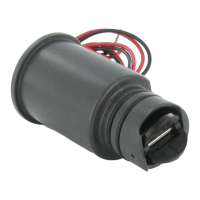
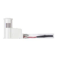
Details the impeller, O-rings, and wires of the Flow-Clik sensor.

Flow-Clik Sensor Body Components

Lists components of the sensor body like Tee, Plug, O-rings, Cap, and Cover.

Flow-Clik Interface Box Components

Flow-Clik System Status Indicator

Installing the Flow-Clik Sensor Body

Installing the Flow-Clik Sensor into the Sensor Body

Step-by-step guide to insert the sensor into its body.

Mounting the Flow-Clik Interface Box

Wiring the Flow-Clik to the Irrigation System

Wiring the Sensor to the Interface Box

Connects the Flow-Clik sensor wires to the Interface Box.

Wiring the Interface Box to the Controller

Details wiring the Interface Box to different types of Hunter controllers (Pro-C, ICC, SRC).

Programming the Flow-Clik Interface Box

Calibrating the Flow-Clik to the Irrigation System

Step-by-step guide for calibrating the Flow-Clik to the system's highest flow zone.

Flow Estimate Calibration Method

Method for estimating flow if the highest flow zone is unknown.

Setting the Startup Delay

Setting the Interrupt Period

Troubleshooting Guide

Troubleshooting Flow-Clik Operation Issues

Addresses issues like the system not shutting off or shutting off unexpectedly.

Troubleshooting Indicator and Sensor Issues

Solves problems related to the system status indicator and sensor functionality.

Specifications

Related product manuals