Do you have a question about the Hunter RAIN CLIK WR-CLIK and is the answer not in the manual?
Unique technology that turns off irrigation immediately upon detecting rain.
Provides trouble-free operation for up to ten years without battery replacement.
Wireless operation up to 800 ft (275 m) without wires between sensor and controller.
WR-CLIK for rain shutoff, WRF-CLIK adds freeze protection below 37°F.
Transmitter sends signals hourly to ensure continuous synchronization with the receiver.
Sensor Bypass LED flashes RED if receiver loses signal from transmitter.
Used to press and hold to confirm proper operation of the transmitter.
Adjusts reset rate or dry-out time for the sensors by opening/closing vents.
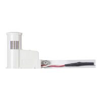
Transmits a wireless signal to the receiver up to 800 ft (275m).
Metal extension arm for mounting the sensor.
Used to determine the status of the sealed battery; flashes to indicate good battery.
Allows automatic or manual watering when the sensor is active.
Indicates when the sensor has been bypassed.
Indicates the status of the sensor (dry/wet).
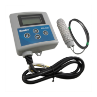
Receives a wireless signal from the transmitter up to 800 ft (275m).
Two yellow wires attached to a 24 VAC source from the controller.
Wires attached to sensor terminals in the controller or in-line with valve common wire.
Explains use of Blue/White (normally closed) and Blue/Orange (normally open) wires.
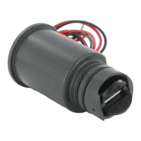
Used to protect the receiver when mounted in outdoor locations.
Mount receiver near controller, away from interference. Attach rubber cover.
Specific instructions for connecting receiver wires to a Hunter SRC controller.
Instructions for connecting receiver to specific Hunter controller models.
Instructions for connecting receiver to Hunter ACC controller and using its settings.
Instructions for wiring the receiver for normally closed sensor applications.
Instructions for wiring the receiver for normally open sensor applications.
Wiring for systems with 24 VAC solenoids and a booster pump.
Mount transmitter on a surface exposed to rain, oriented upright.
Using the SGM accessory to mount the transmitter directly to a gutter edge.
Tips for optimal location to ensure good reception and accurate temperature sensing.
How mounting location affects the sensor's dry-out time for system reset.
Notes that there is no setup required for the transmitter.
Explains the meaning of RED, GREEN, and YELLOW lights on the receiver.
Explains the meaning of RED, OFF, and FLASHING RED states of the bypass LED.
How to use the receiver's bypass button to temporarily disable the sensor.
Procedure to pair transmitters and receivers purchased separately.
Step-by-step process for the receiver to learn a new transmitter address.
Information on the transmitter's 10-year battery life and replacement procedure.
Procedure to check the transmitter's battery status using the quick response spindle.
Common causes and checks for when the irrigation system fails to start.
Checks for issues causing the system to not shut off during heavy rainfall.
Diagnosis for when the Sensor Bypass LED is flashing red, indicating communication loss.
States the FCC ID and the two conditions for device operation.
Lists trade name, model number, test report, responsible party, and contact info.
Signature, place, full name, and position of the declarant.
Lists IC IDs for sensor/receiver and the two conditions for operation.
Declares compliance with essential requirements and lists relevant emission/immunity standards.
| Brand | Hunter |
|---|---|
| Model | RAIN CLIK WR-CLIK |
| Category | Accessories |
| Language | English |