Wireless Rain-Clik
™
Rain Sensors
Installation Instructions
INTRODUCTION
In most installations, the Wireless Rain-Clik™ acts as a switch to break the
circuit to the solenoid valves of the irrigation system when it has rained. This
allows the timer to advance as scheduled, but keeps the valves from opening
the water ow. Once the Wireless Rain-Clik has dried sufciently, the switch
closes again to allow for normal operation.
CONTENTS
Included with the Wireless
Rain-Clik are the following items:
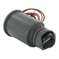
1. Sensor body with Transmitter
2. Telescoping extension arm
3. Wall mount / Conduit adapter
4. Gutter clip
5. Mounting Hardware
6. Receiver
7. Cover for Receiver
MOUNTING
Standard Mount:
Using the screws provided, mount the Wireless Rain-Clik transmitter on any
surface where it will be exposed to unobstructed rainfall, but not in the path of
sprinkler spray. The switch-housing portion must be upright (as pictured), but
the swivel-bracket can be moved for mounting on any angled surface.
Gutter Mount:
Clip the enclosed gutter mounting bracket over the inside lip of the gutter.
Attach the Wireless Rain-Clik to the gutter mounting bracket with the screws
provided.
Helpful Hints for
Mounting:
A. When looking for a
suitable location such
as on the side of a
building or post, the
closer the Wireless
Rain-Clik is to the
controller, the better
reception will be. DO
NOT EXCEED 300
feet.
B. The ideal location for
mounting is not always
the most practical
location. In the case
where a compromise
must exist (such as
low location on a
side wall rather than
the preferred high
location), note that
the Wireless Rain-Clik
will still work as it will
always receive some
rainfall – it just will not
be as accurate in its
gauging as it could be.
C. As described in the
“Operation” section
of this manual, “reset
rate” refers to the
amount of time it takes
the Wireless Rain-Clik
to dry out sufciently
for the sprinkler system
to be allowed to come back on. The mounting location will affect this rate
and should be taken into consider-ation should extreme conditions exist. For
example, mounting the Wireless Rain-Clik on a very sunny, southern end of
a building may cause the Wireless Rain-Clik to dry out sooner than desired.
Similarly, mounting on the northern end of a building with constant shade
may keep the Wireless Rain-Clik from drying soon enough.
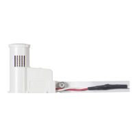
Transmitters/Sensor
• Nothing to set up with this unit after installation
• The unit can be tested stand-alone as follows: press and hold the post on
the quick response section. Within 3 seconds of pressing and holding this
post down, the LED protruding from the potting should blink once. Release
the post, within 3
seconds the LED
should blink once
again. (Figure 1)
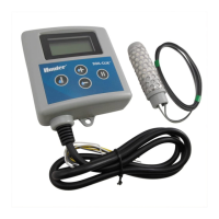
Receiver
• Using the hardware
included, mount the
receiver to the wall
(use included wall
anchors if needed).
Make sure to put the
rubber cover/gasket
under the unit when
attaching it in an
outdoor location.
WIRING TO YOUR IRRIGATION SYSTEM
WARNING! This unit is designed to be installed in conjunction with 24VAC
circuits only. Do not use with 110 or 220VAC circuits.
Receiver Installation, SRC Controller: (See Figure 2)
1. Attach the two yellow
wires to the AC terminals
of the SRC (polarity does
not matter).
2. Attach the blue wire to the
RS terminal.
3. Attach the white wire to
the “C” terminal.
4. Attach the valve common
wire to the RS terminal.
Receiver Installation,
Pro-C and ICC Controllers:
(See Figure 3)
1. Attach the two yellow
wires to the AC terminals
of the controller (polarity
does not matter).
2. Attach the blue wire to
one SEN terminal and
the white wire to the
other SEN terminal of the
controller.
Receiver Installation, Other
Controllers:
A. Normally Closed
Sensor Applications
(See Figure 4)
1. Attach the two yellow
wires to the AC terminals
of the controllers (polarity
does not matter).
2. To attach the receiver
to this type of controller,
attach the blue wire and
the white wire to the
sensor terminals of the
controller, or in-line with
the valve common.
B. Normally Open Sensor
Applications
1. A few controllers on the
market require a normally
open rain sensor. To
attach the receiver to
this type of controller,
attach the blue wire and
the orange wire to the
controller’s sensor input.
Gutter
Mount
Standard
Mount
Figure 1
Manually depress the spindle at
the top of the Wireless
Rain-Clik
Wireless
Rain Sensor
Hunter SRC
Figure 2
R RS C 1ACAC 2 3
W
B
Y
Y
Common Wire
to all Valves
Red light indicates
sensor is bypassed
GREEN = Sensor is dr
y
RED = Sensor is wet
SENSOR BYPASS
SENSOR STATUS
WIRELESS
RAIN SENSOR
RAIN SENSOR
Press to bypass, press
again to re-enabl
e
Figure 3
Wireless
Rain Sensor
Hunter ICC/Pro-C
SEN
SEN
C
TEST
P MV
AC
AC
G
REM
Red light indicates
sensor is bypassed
GREEN = Sensor is dr
y
RED = Sensor is wet
SENSOR BYPASS
SENSOR STATUS
WIRELESS
RAIN SENSOR
RAIN SENSOR
Press to bypass, press
again to re-enabl
e
B
W
Y
Y
Controller
Figure 4
P MVC
Wireless
Rain Sensor
AC AC
W
B
Y
Y
Common Wire
to all Valves
Red light indicates
sensor is bypassed
GREEN = Sensor is dr
y
RED = Sensor is wet
SENSOR BYPASS
SENSOR STATUS
WIRELESS
RAIN SENSOR
RAIN SENSOR
Press to bypass, press
again to re-enable
➀
➂
➃
➄
➁
Red light indicates
sensor is bypassed
GREEN = Sensor is dr
y
RED = Sensor is wet
SENSOR BYPASS
SENSOR STATUS
WIRELESS
RAIN SENSOR
RAIN SENSOR
Press to bypass, press
again to re-enable
➆➅