2
This section will give you a brief overview of some of the
components of the Flow-Clik system. Each item will be
discussed in further detail later, however, this section can
be helpful in getting acquainted with the different options
available.
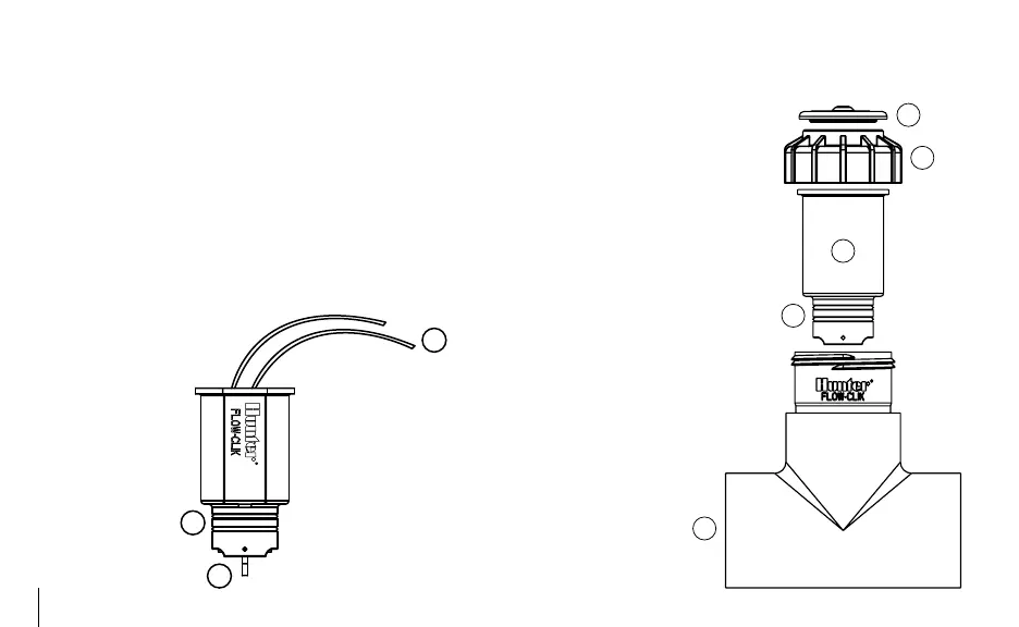
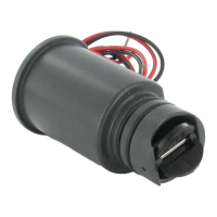
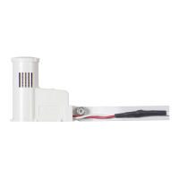
A. Flow-Clik Sensor
1. Impeller – rotates when flow is occurring
2. O-rings – provides sealing of sensor in sensor body
3. Wires – black and red wires connect sensor to
Flow-Clik Interface Box
B. Flow-Clik Sensor Body (FCT Series)
4. Flow-Clik Tee – the Tee
is installed into the irriga-
tion system and houses the
Flow-Clik sensor
5. Plug – used to seal the
body when the sensor is not
installed in the sensor body
6. O-rings – provides sealing of
plug in sensor body
7. Cap – retains plug or sensor
in sensor body
8. Cover – snaps over the top of
the sensor
Note: Flow-Clik sensor bodies
ordered separately.
FLOW-CLIK COMPONENTS............................................................................