14
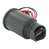
Other Controllers
1. Attach the two yellow wires to the AC terminals on the
controller (polarity does not matter).
2. Some controllers do not have terminals dedicated for
sensor installations. Locate the common wire to the
solenoid valves and disconnect it from the common
terminal (usually marked “C” on the controller). Attach
one white wire from the Flow-Clik Interface Box to the
common terminal. Attach the other white wire to the
common wire leading to the valve.
WIRING THE FLOW-CLIK TO THE IRRIGATION SYSTEM (continued)...
WIRING WHEN USING MULTIPLE SENSORS ............................................
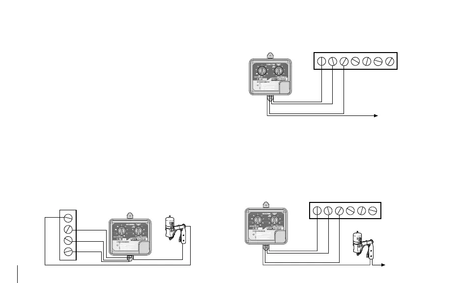
The Flow-Clik can be wired to a controller already using
another Hunter sensor (i.e. Rain-Clik™, Wind-Clik
®
,
Freeze-Clik
®
, etc.) or other micro-switch type sensors. It is
important to make sure that, when using multiple sensors,
they are connected in series.
Interface Box
Common Wire
to All Valves
Y
W
Y
W
1 2 3 4
Controller
CAC AC
Hunter Controllers
Mini-Clik
AC
AC
SEN
Interface Box
SEN
Y
Y
W
W
1 2 3
Interface Box
C
Common Wire
to All Valves
AC AC
Y
W
Mini-Clik
Y
W
Other Controllers