12
WARNING! This unit is designed to be installed in conjunc-
tion with 24 VAC circuits only. Do not use with 110 or 220
VAC circuits.
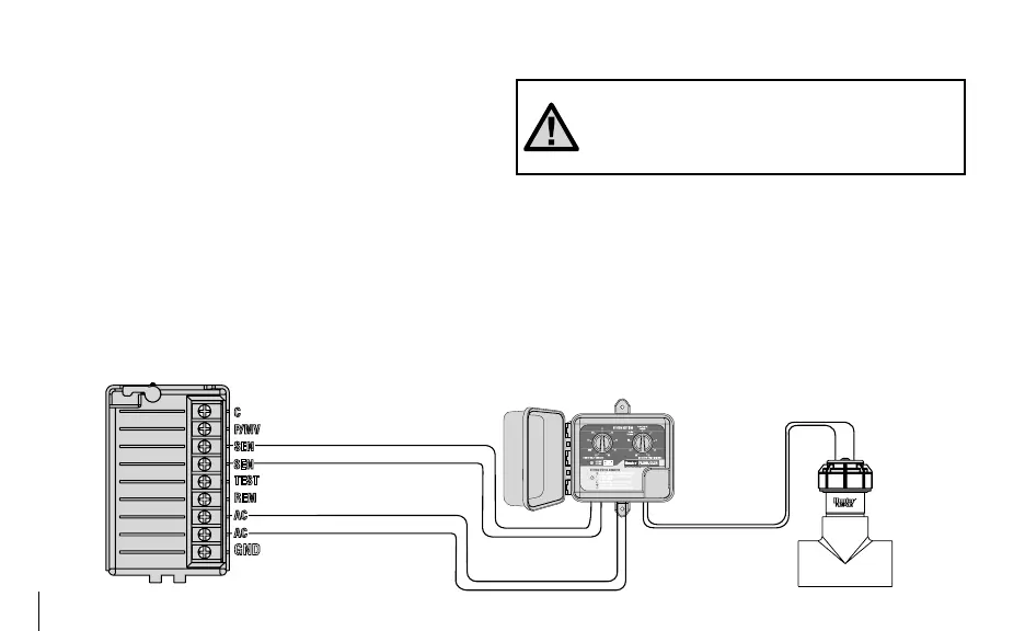
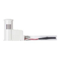
Wiring the Sensor to the Interface Box
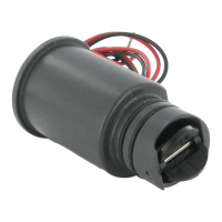
The red and black leads from the Flow-Clik sensor are
connected to the red and black leads on the Interface Box.
A minimum wire size of 18-gauge wire can be used to con-
nect the leads from the sensor to the Interface Box. Secure
all wire connections with waterproof connectors.
Note: The Flow-Clik Sensor can be installed
up to a maximum of 1,000 ft. from the Inter-
face Box when installed with #18 gauge or
larger copper wire.
WIRING THE FLOW-CLIK TO THE IRRIGATION SYSTEM ........................
Flow-Clik Interface Box Flow-Clik Sensor
Hunter Controller
Power Module (Typical)
Yellow
Yellow
Sensor Loop
24 VAC Power
White
White