3
10
11
12
9
13
14
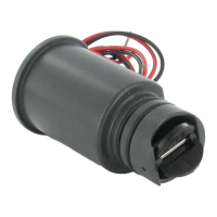
Black
Red
To Sensor
To 24 VAC Terminals in Controller
To Sensor Terminals in Controller
Yellow
White
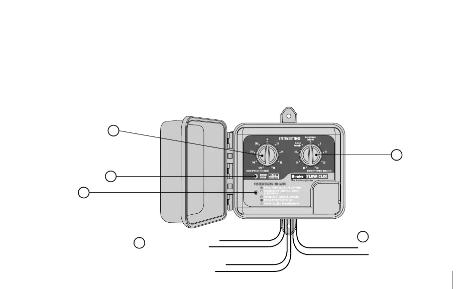
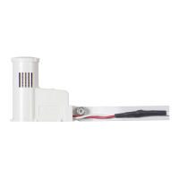
C. Flow-Clik Interface Box
9. Startup Delay Rotary Dial – used to set startup delay
and calibrate sensor
10. Interrupt Period Rotary Dial – used to set interrupt
period and calibrate sensor
11. Restart/Calibrate Button – used to restart system
(when using the “Restart Manually” setting) and cali-
brate sensor during setup
12. System Status Indicator – provides a visual indication
of the Flow-Clik status
13. Wires – black and red wires to Flow-Clik Sensor
14. Wires – yellow wires to AC power terminals at Control-
ler, white wires to sensor or common terminals at
controller