The Hunter Flow-Sync (HFS) is a flow sensor designed for use with compatible Hunter controllers, such as the Hunter ACC and I-Core, to monitor actual flow in irrigation systems. It allows flow-capable controllers to record and report actual flow in liters or gallons. With proper setup, the controller can use Flow-Sync to learn typical flow for each zone of irrigation and monitor during watering for high and low flow conditions. Flow-Sync equips controllers to respond to incorrect system performance, preventing damage to landscape and wasted water resources.
Function Description:
The Flow-Sync operates by means of an impeller that rotates when flow occurs. As the impeller turns, pulses are generated and sent to the controller. The controller then converts these pulses into gallons or liters, depending on the Units of Measurement selection. Flow-Sync is a reporting device and does not respond to flow situations on its own. It is almost always installed in conjunction with a Master Valve, which can stop flow in a damaged pipe when high flow conditions are detected. The sensor connects to the controller via two direct burial-rated 18 AWG/1 mm wires, up to 1000 ft/300 m away. It can also connect to ACC99D family decoder controllers via the ICD-SEN sensor decoder, reporting up the same two-wire path used by ICD station decoders. Flow-Sync does not require any additional power source.
Important Technical Specifications:
-
Operating Specifications:
- Temperature: 0 to 140°F/60°C
- Pressures: up to 200 psi/13.7 bar
- Humidity: up to 100%
-
Flow Range (Gpm):
- 1" Flow-Sync Sensor Diameter: Minimum 2, Suggested Maximum 17
- 1½" Flow-Sync Sensor Diameter: Minimum 5, Suggested Maximum 35
- 2" Flow-Sync Sensor Diameter: Minimum 10, Suggested Maximum 55
- 3" Flow-Sync Sensor Diameter: Minimum 28, Suggested Maximum 120
- 4" Flow-Sync Sensor Diameter: Minimum 34, Suggested Maximum 195
- Minimum recommended flow for the highest flow zone for your system.
- Good design practice dictates the maximum flow not to exceed 5ft/sec. Suggested maximum flow is based upon Class 200 IPS plastic pipe.
-
Maximum Distance Between Controller/Sensor Decoder and Sensor: 1000 ft/300 m
-
Wire: 18 AWG/1 mm, 36"/1 m leads (Ø = diameter)
-
Dimensions (FCT Tee Fitting):
- FCT 100: Height 4.8"/12 cm, Width 2.3"/6 cm, Length 4.5"/11 cm, Straight Pipe upstream (Ø x 10) 10"/25 cm, Straight Pipe downstream (Ø x 5) 5"/13 cm
- FCT 150: Height 5.4"/14 cm, Width 2.3"/6 cm, Length 4.6"/12 cm, Straight Pipe upstream (Ø x 10) 15"/38 cm, Straight Pipe downstream (Ø x 5) 8"/20 cm
- FCT 158: Height 5.4"/14 cm, Width 2.3"/6 cm, Length 5.1"/13 cm, Straight Pipe upstream (Ø x 10) 15"/38 cm, Straight Pipe downstream (Ø x 5) 8"/20 cm
- FCT 200: Height 6"/15 cm, Width 2.7"/7 cm, Length 4.7"/14 cm, Straight Pipe upstream (Ø x 10) 20"/50 cm, Straight Pipe downstream (Ø x 5) 10"/25 cm
- FCT 208: Height 6"/15 cm, Width 2.7"/7 cm, Length 5.4"/14 cm, Straight Pipe upstream (Ø x 10) 20"/50 cm, Straight Pipe downstream (Ø x 5) 10"/25 cm
- FCT 300: Height 7"/18 cm, Width 4"/10 cm, Length 6.2"/16 cm, Straight Pipe upstream (Ø x 10) 30"/76 cm, Straight Pipe downstream (Ø x 5) 15"/38 cm
- FCT 308: Height 7"/18 cm, Width 4.2"/11 cm, Length 6.4"/16 cm, Straight Pipe upstream (Ø x 10) 30"/76 cm, Straight Pipe downstream (Ø x 5) 15"/38 cm
- FCT 400: Height 8"/20 cm, Width 5"/13 cm, Length 6.2"/16 cm, Straight Pipe upstream (Ø x 10) 40"/1 m, Straight Pipe downstream (Ø x 5) 20"/50 cm
-
Flow Sensor Values (K-Factor and Offset for HFSFCT models):
- HFSFCT100: K-Factor 0.44, Offset 0.39
- HFSFCT150: K-Factor 1.13, Offset 0.00
- HFSFCT158: K-Factor 0.92, Offset 1.22
- HFSFCT200: K-Factor 2.13, Offset 0.23
- HFSFCT208: K-Factor 1.72, Offset 1.70
- HFSFCT300: K-Factor 4.61, Offset 0.18
- HFSFCT308: K-Factor 5.87, Offset 1.07
- HFSFCT400: K-Factor 8.77, Offset 0.48
Usage Features:
-
Installation: The Flow-Sync Sensor is designed to install within an FCT tee fitting, sized for the pipe in which it will be installed. FCT Tees are ordered separately based on desired pipe diameter. For international applications, optional slip-BSP adapters are available.
- Install the FCT tee fitting first, then the Flow-Sync Sensor.
- Flush the system with a plug in place before installing the Flow-Sync sensor to prevent damage to the impeller.
- Always install Flow-Sync together with a Master Valve for overflow protection.
- Install the Flow-Sync and Master Valve as near the point of connection to the water supply as possible.
- Flow-Sync requires a section of straight pipe on either side of the tee fitting to provide accurate measurement of flow. Tees, ells, and other fittings cause turbulence which affects accuracy.
- There must be a length of straight pipe at least 10 times the diameter of the pipe upstream from the Flow-Sync (toward the water supply).
- There must be a length of straight pipe at least 5 times the diameter of the pipe in the downstream direction (toward the sprinklers).
- The FCT tee fitting is designed for glue ("slip") connection. Use approved PVC solvent-welding glue. Metric thread adapters are available.
- Caution: Avoid excess glue when attaching fittings, as uncured blobs of excess glue on the fitting's interior can interfere with paddlewheel operation.
- Installation Steps for Sensor into FCT Fitting:
- Turn the system pressure off.
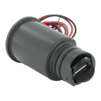
- Unscrew the cap from the top of the FCT (figure 1).
- Use pliers or a screwdriver to carefully pry the plug from the FCT tee.
- Insert the sensor into the FCT. The sensor has a flat side that engages with a flat on the inside of the sensor body (figure 2).
- Replace the cap on the sensor body. Hand tighten only (figure 3).
- Feed the two sensor wires through the hole in the cover and snap the cover on the cap.
- Note: Do not attempt to remove the sensor plug or sensor while the system is under pressure.
- Note: Never glue the HFS sensor into the fitting! The threaded cap is designed to seal under pressure.
-
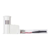
Wiring: Flow-Sync is designed for low-voltage connection to approved irrigation controller flow terminals (not high-voltage 110V or 230V circuits).
- The red and black lead wires from the Flow-Sync Sensor are for DC voltage. The red wire is positive (+) and the black wire is negative (-).
- When extending wires, observe red and black wire polarity. Use an extension wire with a similar color code.
- Connect the red lead from the sensor to the red (+) flow terminal in the controller. Connect the black lead from the sensor to the black (-) terminal in the controller. Use quality waterproof connectors for all wire connections.
- In ACC controllers, terminals are marked "Flow," one for red and one for black.
- In I-Core controllers, terminals are marked either S1 (one is red, one is black) or S2 (or S3 in metal versions).
- When used with a Hunter ICD-SEN sensor decoder, consult the manual for the ICD-SEN.
- Flow-Sync may only be used on Port A of a sensor decoder.
- Cut the purple loop (Port A) on the sensor decoder.
- Observe polarity: when the loop is cut, the lead on the station label side of the ICD-SEN is the negative (-) side.
- Connect the black wire from Flow-Sync to the negative side of the decoder port, and connect the red wire to the positive side of the port.
- Finish configuration as described in the ICD-SEN and ACC controller documentation.
- Note: The Flow-Sync Sensor can be installed up to a maximum of 1,000 ft/300 m from the controller when installed with 18 AWG or 1 mm gauge or larger copper wire.
-
System Considerations:
- Hunter flow-capable controllers measure and record actual flow, shut off irrigation when a high flow condition occurs, and identify which stations caused the condition.
- The controller's Learn mode samples each station individually and learns a typical flow. Actual flows are recorded and stored in the controller facepack. The ACC or I-Core controller compares actual flows to the estimated total of all active stations to detect unacceptable differences (leaks or breaks).
- Consult controller documentation for setup and operation of flow monitoring.
- Set adequate overage amounts (minimum 15% over normal) and delays (default one minute) to prevent false alarms.
- Mainline Pressure Fluctuation: Some water sources may have varying pressure depending on demand. Heavy demand can cause system pressure through the mainline to drop. This is why flow limit percentage and delay periods (set in the controller) are important, as false alarms lead to a lack of confidence in the system.
- Excess air in irrigation piping causes the Flow-Sync impeller to spin freely during station startup, which may cause temporarily high readings. This can be reduced by installing check valves and setting alarm delay values.
-
Calibration: Hunter controllers allow selection of the correct pipe size by FCT model number. No further calibration is needed. If "Other" is selected, K-factor and Offset information may be entered directly.
Maintenance Features:
- Proper System Maintenance and Operation: It is important that your irrigation system be maintained and is functioning properly for optimum performance. Check your irrigation system for any broken components or leaks, and ensure all sprinklers are operating within the pressure ranges recommended by the manufacturer.
- Troubleshooting Guide:
- Flow-Sync not reading:
- Cause: Water shut off. Solution: Verify no isolation valves are closed and water source is on.
- Cause: Controller not configured. Solution: Check controller flow sensor setup. Enter sensor size (and location, for sensor decoders) and other sensor information as required.
- Cause: Faulty Wiring. Solution: Use a voltmeter to verify red and black wires are connected and not reversed. Fix any wire splices. Correct polarity (red and black).
- Cause: Damaged sensor (debris in water) or Flow-Sync electronics damage (lightning). Solution: Replace sensor.
- Flow-Sync not reading correctly:
- Cause: Controller configured incorrectly. Solution: Set correct flow sensor size and type at controller.
- Cause: Turbulent flow at sensor. Solution: Insure straight pipe is on either side of flow meter.
- Frequent false alarms:
- Cause: Station settings too sensitive. Solution: Increase overflow percentage (and underflow if available).
- Cause: Wide range of flows for a single station. Solution: Increase overflow and underflow percentages, and delay interval.
- Impeller Protection: Flow-Sync has an impeller which will turn in the flow of water. If the water source is not a public water supply, add a filter upstream from the Master Valve and Flow-Sync to protect the impeller from rocks or stones, which may damage the impeller.