1 - 20 Machine Components 704-0212-209 VM Series Maintenance and Safety Manual
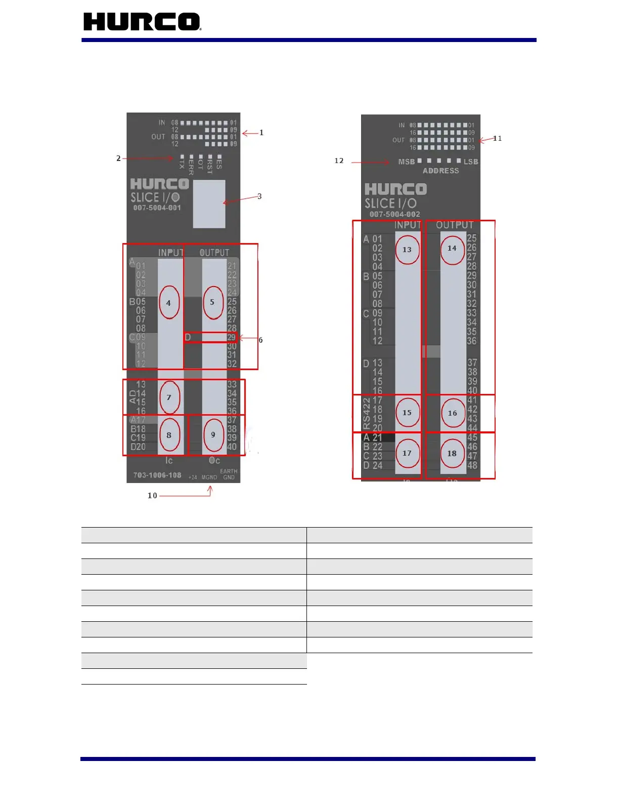
The following figure identifies the components of the Slice 0 and Slice 1 I/O devices:
Figure 1–4. Slice I/O
(Main) Slice 0
(Slave) Slice 1
1 I/0 Status LEDs 11 I/0 Status LEDs
2 System Status LEDs 12 Slice Address (binary)
3 RJ45 CAN 13 16 Inputs
4 12 Inputs 14 16 Outputs
5 12 Outputs 15 (2) RS422 Inputs
6 OUT9 (COR) 16 (2) RS422 Outputs
7 4 A/D Inputs 17 Input Bank Commons
8 Input Bank Commons 18 Output Bank Commons
9 Output Bank Commons
10 Clean 24V Power In
 Loading...