WinMax Lathe NC Programming 704-0115-307 ISNC G Codes 4-29
Cutter Compensation (G40–G42)
Cutter compensation may be used for two purposes. First, it may be used when the
dimensions in the program and the part surface are the same. The system calculates the
proper tool path by using the part surface and the tool diameter information.
Second, cutter compensation corrects the difference between the diameters of the tool
specified and the tool actually used to cut the part. This situation often occurs when the
program originates from an off-line device. Note that the coordinates of those programs
are usually tool center line data.
Cutter compensation is based on the direction of travel of the tool. To determine which
type of cutter compensation to use, look at the part as if you are moving around the part
always keeping the tool ahead of you. Then it becomes obvious whether the tool needs to
be on the right or the left of the programmed line or the boundary of the part
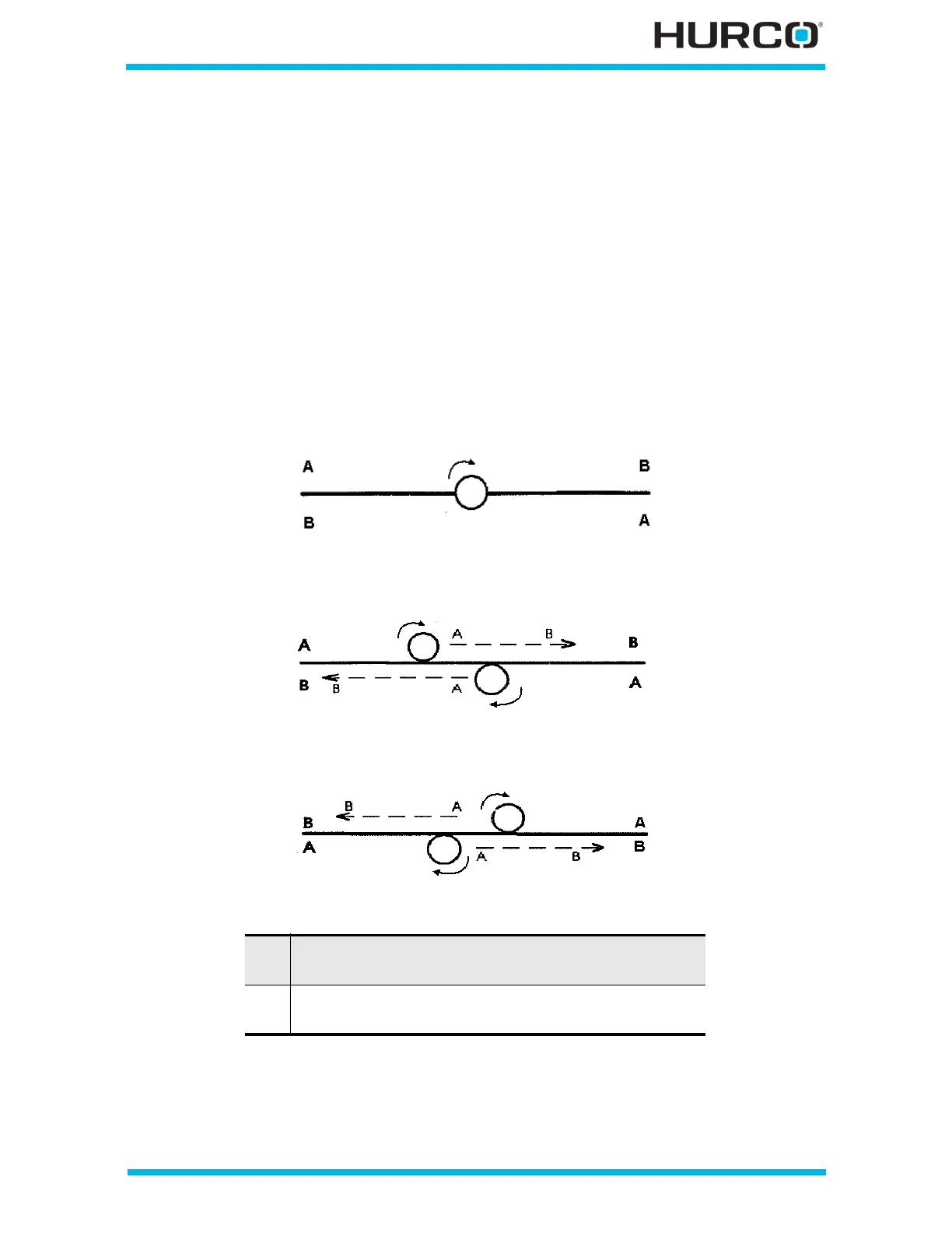
Figure 4–12. G40 Cutter Compensation Off
Figure 4–13. G41 Cutter Compensation Left
Figure 4–14. G42 Cutter Compensation Right
A Beginning point of programmed direction
(clockwise tool movement from point A to point B)
B Ending point of programmed direction
(clockwise tool movement from point A to point B)

 Loading...

