11
4.3 Circuit diagram
4.4 Control of the operating movements
4.5 Hydraulic supply
4.6 Hoses
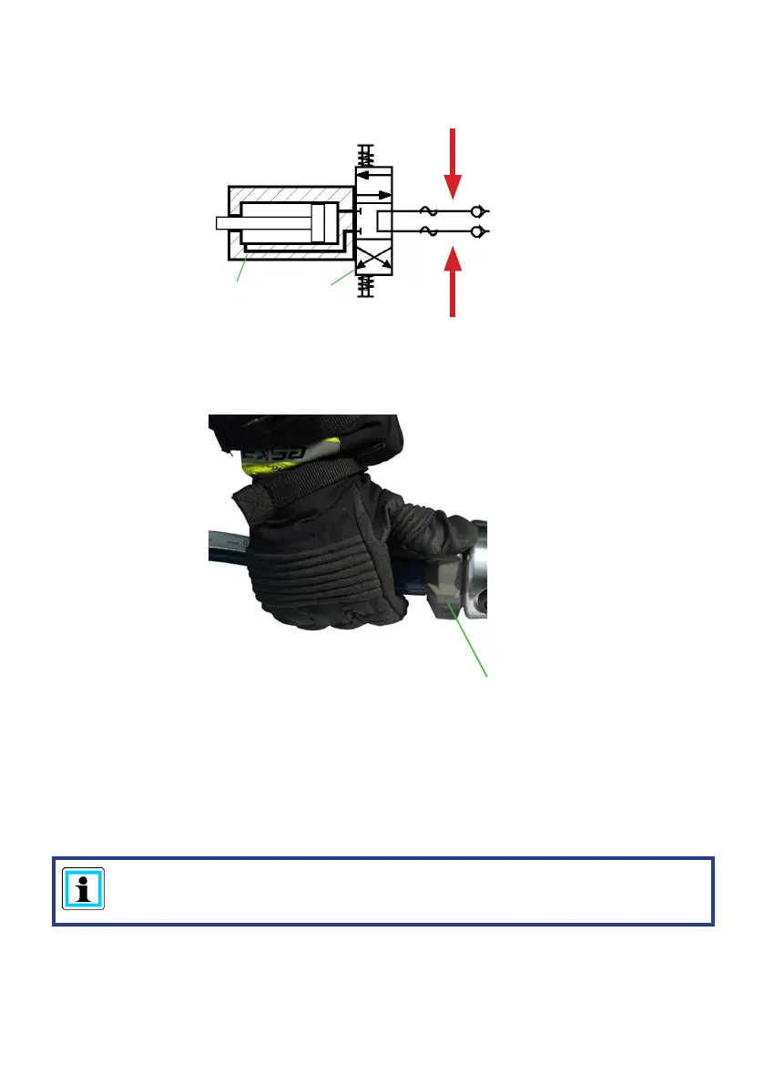
A
B
spreading
pulling /
squeezing
star grip
g. 3
To enable comprehension of the function, a simplied hydraulic cylinder of the rescue
equipment (A) + hand valve (B) are depicted here.
The spreading arms movement is controlled via the star grip of the mounted valve.
(see cover, item 1 and, below, gure 3).
A HURST motor pump or hand pump only may be used to drive the equipment.
If the pump unit is a dierent make, you must make sure that it complies with HURST
specications, otherwise potential dangers may occur which are not the responsibility of
HURST.
Ensure in particular that the authorised operating pressure for HURST equipment is not
exceeded.
REMARK:
Before you use pumps from a dierent manufacturer, you must contact HURST
or an authorised dealer.
The pump unit and the rescue tool are connected by hoses.