6 | DOC-532_EN REV04 ORIGINAL INSTRUCTIONS
NOTE
» APPLICABLE TO ALL POWER UNITS: in order to avoid overheating, we
recommend 12 in / 30 cm clearance all around the power unit�
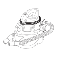
Fig. 1 Low voltage technology hose.
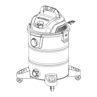
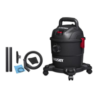
3. MODEL
Mandatory
disposable
ltration bag
Filtration bag
support pad
Internal control
module
Air intake
Air outlet
POWER UNIT
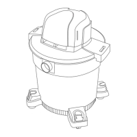
24-50" /
61-127 cm
16" / 40 cm
3/4" / 2 cm
Mounting
Board
at least
10" / 25 cm
Mounting
Bracket
Fig. 2 Mounting the power unit on the wall.
The power unit must be installed in a ventilated area, easily accessible and away from any heat
source. It should also be close to an accessible electrical outlet.
1� Determine the location of the power unit on the wall; we recommend that the power unit
be fastened at 24 -50” / 61-127 cm above ground in order for the top cover to be readily
accessible. Moreover, allow a minimum clearance of 20” / 50 cm on top.; allow 12” /
30cm clearance on all sides of the power unit. When possible, it is advisable to install
the power unit on a concrete wall in order to minimise the vibrations;
2� Gypsum wall:
• Prepare the wall by installing a plywood mounting board (not provided) 16” / 40 cm high
x 3/4” / 2 cm thick and wide enough to be screwed to at least 2 studs;
• Fasten the mounting bracket to the mounting board with the provided screws;
3� Concrete wall:
• Drill the holes with a concrete drill bit;
• Insert the provided wall anchors into the drilled holes;
• install the mounting bracket with the provided screws into the anchors;
NOTE
» You may also install a plywood mounting (16” / 40 cm x 10” / 25 cm x
3/4” / 2 cm) board if desired;
» You can use provided screws to x mounting board on the wall, but
cannot use them for installing the mounting bracket on the mounting
board because of their length� You need to use shorter screws (not
provided)�
IMPORTANT
Always use the right type of screws for the surface you are working with (wood,
concrete, metal…)
4� Insert the power unit bracket into the mounting bracket (as shown in Fig. 2).
5� Insert the PVC pipe into the air intake coupling; DO NOT GLUE!
6� OPTIONAL - If you plan on conducting the exhaust towards the exterior, secure PVC piping
to the air outlet all the way to the outside.
7� Connect the control module (see section 5);
8� Connect the power unit directly into an electrical outlet.
4. INSTALLATION
 Loading...