 Loading...
Do you have a question about the Husqvarna Rider PR 17 and is the answer not in the manual?
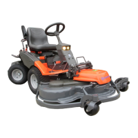
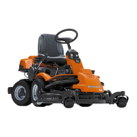
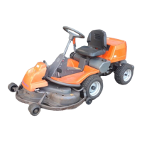
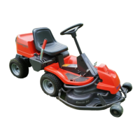
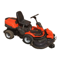
| Transmission Type | Hydrostatic |
|---|---|
| Drive Method | Rear-Wheel Drive |
| Cutting Height Steps | 7 |
| Blades | 3 |
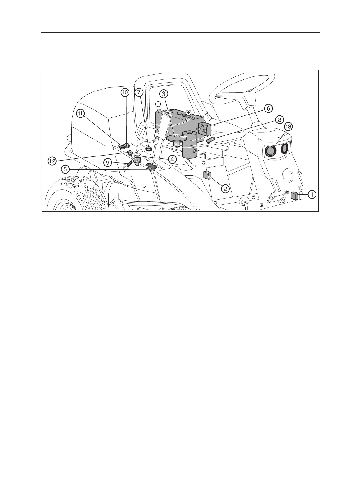
| Hour Meter Type | Digital |
| Seat Suspension | Yes |
| Deck Material | Steel |
| Engine Cooling | Air |
| Fuel Type | Petrol |
| Rear Wheel Size | 16x6.5-8" |
| Collection System | Available as an accessory |