I.34
Part. N. 8000 B0148 (02-2008)
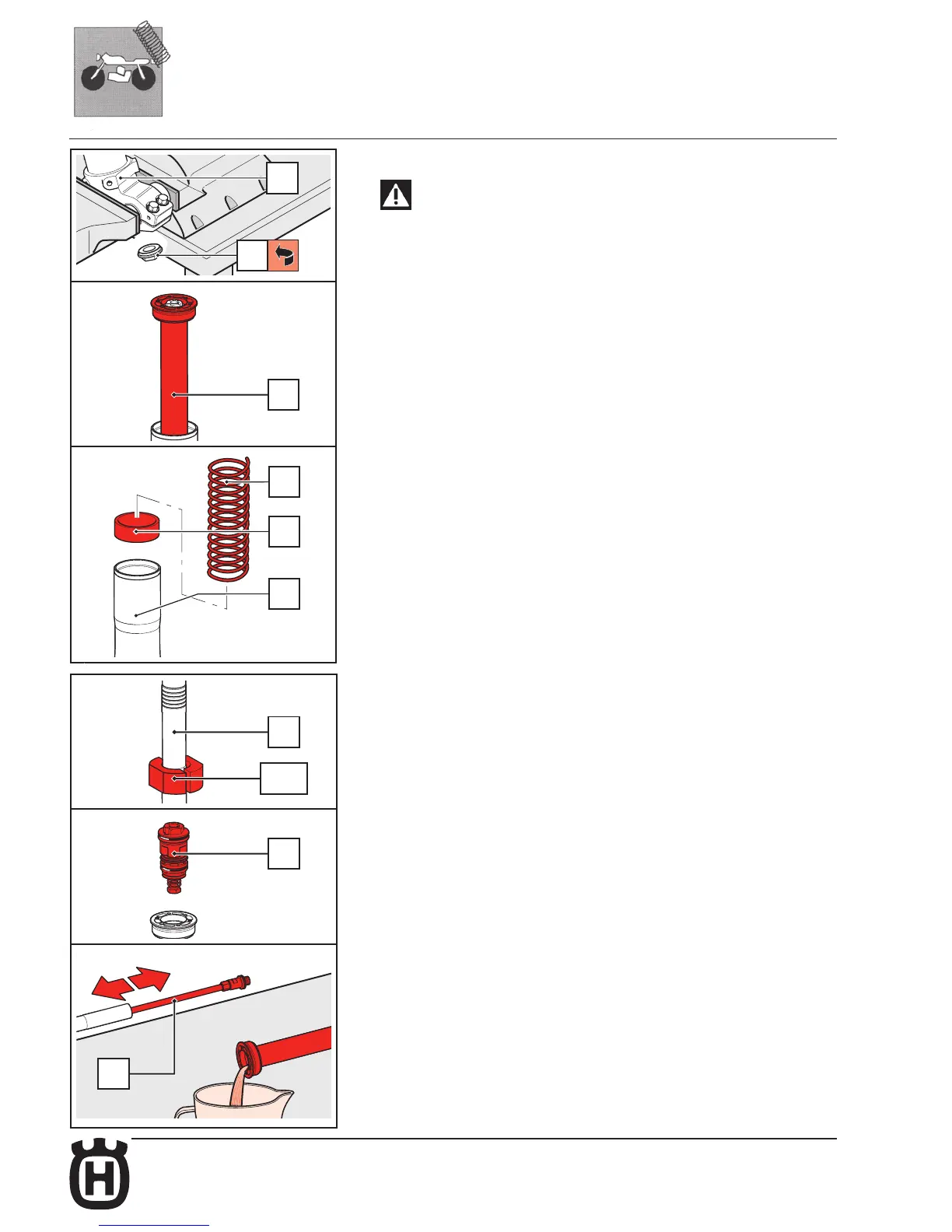
FRONT SUSPENSION
48
70
21
11
17
19
REMOVING THE CARTRIDGE UNIT
WARNING!
This operation must be done only after having drained allof the oil out of the
fork leg.
• Clamp the wheel axle clamp (70) in the vice.
• Unscrew the lower cartridge nut (48) with a 21 mm socket wrench.
• Remove the lower cartridge nut (48).
• Pull the cartridge (21) off the stanchion.
• Remove the spring (19) and the pre-load spacer (17) from inside the slider (11).
OVERHAULING AND MODIFYING THE CARTRIDGE UNIT AND COMPRESSION
VALVE SETTING
Breaking down the cartridge
• Rotate the rebound adjuster in fully closed position (rotate it fully clockwise).
• Fix the cartridge set (21) in the vice by means of the special protection jaws (R5155),
as shown in the figure.
• Use a 21mm spanner to unscrew the compression valve unit (43).
• Remove the complete compression valve unit (43).
• Free the cartridge set from the vice and rotate it into a container of a suitable size
to drain the oil; pump the fork to help the oil flow out while pushing the pumping
element rod (25) forwards and backwards. Fully compress the fork a few times.
R5155
21
43
25

 Loading...