P/N 3034041_D 21
HUSSMANN CORPORATION • BRIDGETON, MO 63044-2483 U.S.A.
VRM Merchandisers
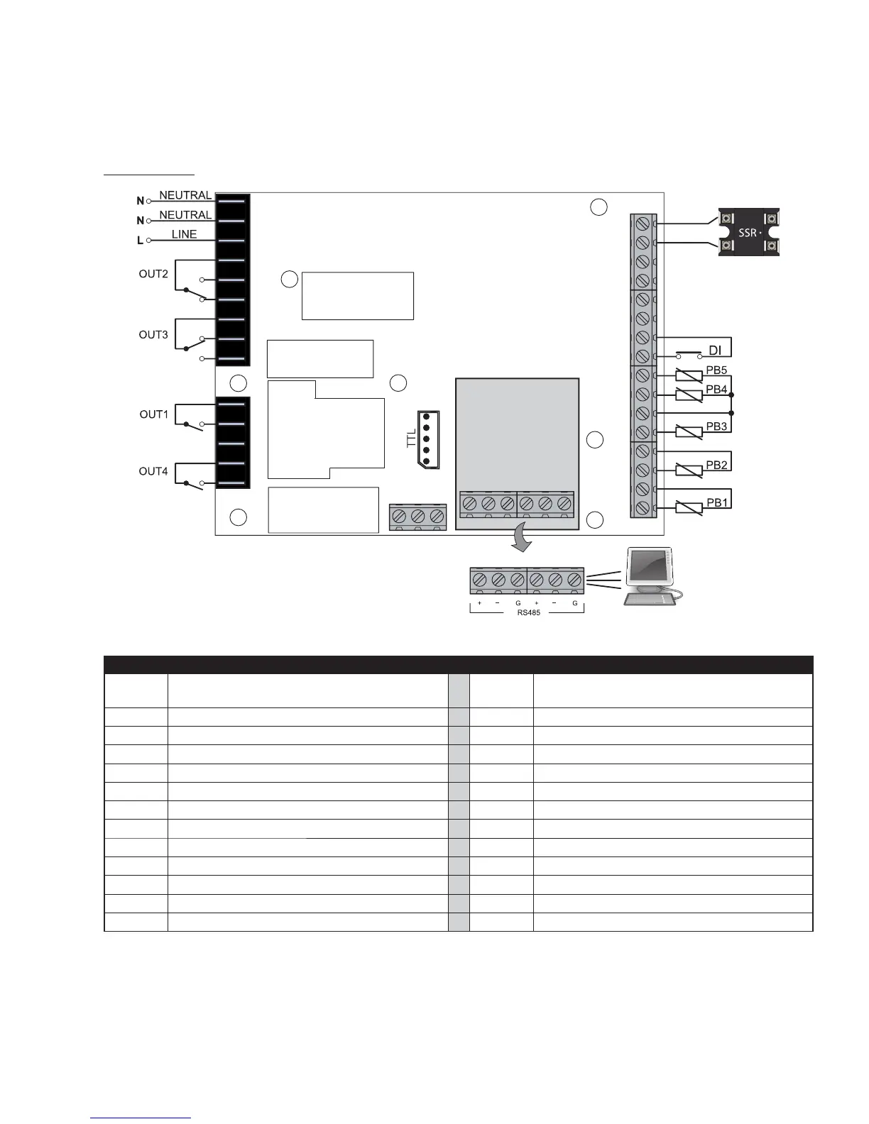
CONNECTIONS
TERMINALS
LINK
2
KEYB
{
{
RS485
OPTIONAL
ELIWELL
ELIWELL
33
32
31
29
30
28
27
26
25
24
22
20
18
23
21
19
1
2
3
5
9
4
11
12
10
GND D
GND
GND
D
OC
12V
D
12V
15 16 17
34 35 36 37 38 39
A
14
13
6
8
7
OUT2 (1HP)
OUT1 (2HP)
OUT3 (8A)
OUT4 (8A)
* N.B.: analogue inputs PB1...PB5 can also be configured as Digital Inputs DI.
TERMINALS
1-2 NEUTRAL.
These are power supply terminals. 15-16-17
Connection to KDEPlus or KDWPlus external
keyboard or ECPlus echo module.
3 LINE. These are power supply terminals. 19-18 PB1 probe connection.
4 OUT2 Shared Terminal 21-20 PB2 probe connection.
5 N.O. OUT2 23-22 PB3 probe connection.
6 N.C. OUT2 23-24 PB4 probe connection.
7 OUT3 Shared Terminal 23-25 PB5 probe connection.
8 N.C. OUT3 27-26 Digital input (DI).
9 N.O. OUT3 28-29 LINK
2
. Connection 1 - local area network.
10 OUT1 Shared Terminal 30-31 LINK
2
. Connection 2 - local area network.
11 N.O. OUT1 32-33 Open Collector Output (OC).
12 Not Used A TTL Unicard/DMI/Multi Function Key connection
13 OUT4 Shared Terminal 34-35-36 RS485. Connection 1 - Supervision Gateway.
14 N.O. OUT4 37-38-39 RS485. Connection 2 - Supervision Gateway.