117373 4-3 REV A
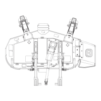
9. Tighten the cap screws under the seat platform on both
sides to lock the drive straight brackets in place. Snug the
cap screws on the top of the steering cover so they don't
move during operation.
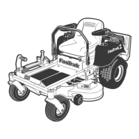
10. IMPORTANT: With the engine off, disconnect the two
female spade connectors from each other (from step #4)
and reconnect them to the seat switch. This must be
completed so that the safety circuit is functioning
properly. Figure 4-7
11. Lower the seat platform and secure in place.
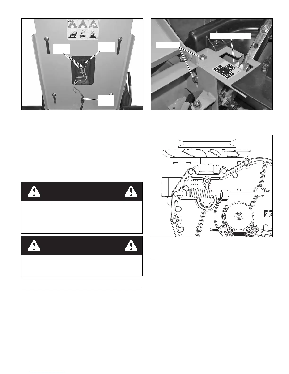
Park Brake Spring Adjustment
Occasionally check the park brake spring adjustment using
the following method:
1. Shut engine off, place steering control levers in the park
brake position, disengage deck clutch, remove ignition
switch key and disconnect negative battery cable before
doing any adjustments.
2. Make sure steering control levers are in the park brake
position.
3. Adjust the nylock nut on the end of the brake rod so that
0.625" of thread is showing. Repeat for other side. Figure
4-9
4. Reconnect the negative battery cable.
5. Close seat platform and re-install seat platform hardware.
Belts
Inspect belts frequently for wear and serviceability. Replace a
belt that shows signs of severe cuts, tears, separation, weather
checking and cracking, or burns caused by slipping. Slight rav-
eling of belt covering does not indicate failure, trim ravelings
with a sharp knife.
Inspect the belt pulley grooves and flanges for wear. A new
belt, or one in good condition, should never run against the bot-
tom of the groove. Replace the pulley when this is the case, oth-
erwise belt will lose power and slip excessively.
Never pry a belt to get it on a pulley as this will cut or damage
the fibers of the belt covering.
Keep oil and grease away from belts, and never use belt dress-
ings. Any of these will destroy the belt composition in a very
short time.
Figure 4-7
WARNING
Do not operate the mower without plugging the mower’s
wiring harness into the seat switch. This switch is an
important part of the safety start interlock system. Serious
injury can result if the seat switch is not plugged into the
mower’s wiring harness.
WARNING
Never operate the mower with a non-functioning seat
switch. Always reconnect the seat switch to the mower
harness.
Mower
harness
Seat
switch
Female
spades
Figure 4-8
Figure 4-9
Cap screws
Drive straight bracket
.625”

 Loading...