606835 3-1 REV B
OPERATION
Safe Operating Practices
Refer to the Safety Precautions section of this manual for
operational and personal safety information.
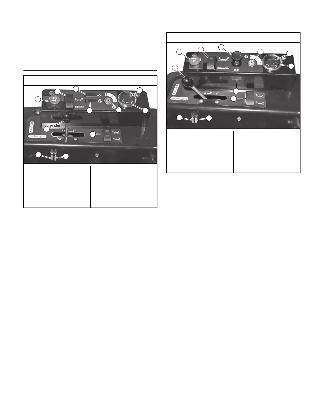
Control Panel
A. Deck clutch switch (Figure 3-1 & Figure 3-2) — this
switch engages the deck. Pull the switch up to engage
and push switch down to disengage the clutch.
IMPORTANT: For additional clutch information refer to
the Mower deck operation section of this manual.
B. Ignition switch (Figure 3-1 & Figure 3-2) — a three
position switch: “OFF”, “RUN”, and “START”. With key
inserted, rotate it clockwise to “START” position;
release key when engine starts, and switch will
automatically return to the RUN position.
C. Oil pressure light (Figure 3-1 & Figure 3-2) — this light
comes on when the ignition switch is placed in the
RUN position and stays lit until the engine is running
and a safe oil pressure is developed. If light comes on
during operation, shut engine off immediately, locate
and correct the problem.
D. Throttle control (Figure 3-1 & Figure 3-2) — a cable is
linked to the engine throttle for controlling engine
speed. Move lever forward to increase engine rpm,
move lever rearward to decrease engine rpm.
E. Choke control (Figure 3-2) — a cable is linked to
manually operate the engine choke. When the lever is
in the down position, the choke is in the “OFF” (“RUN”)
position. When the knob is pulled up, the choke is in
the “ON” (“START”) position. Do not operate the
machine in the “ON” (“START”) position. NOTE: The
choke control is not used on mowers with fuel injected
engines.
F. Electronic hour meter (Figure 3-1, Figure 3-2 &
Figure 3-3) — registers 1/10 hour increments up to
9,999.9 total hours. Connected to the ignition switch,
the meter records the accumulative time while the
ignition key is switched to the RUN position.
G. 20 amp fuse (Figure 3-1 & Figure 3-2) — Controller - 20
amp, blade-type.
H. 15 amp fuse (Figure 3-1 & Figure 3-2) — Ignition &
Safety systems - 15 amp, blade-type.
I. Fuel tank gauge (Figure 3-1, Figure 3-2 & Figure 3-3)
— this gauge shows the fuel level for each fuel tank.
The right gauge indicates the fuel in the right tank and
Mowers with Vanguard EFI engines
A. Deck clutch switch
B. Ignition switch
C. Oil pressure light
D. Throttle
E. Choke
F. Hour meter
G. 20 amp fuse
H. 15 amp fuse
I. Fuel gauge
J. Side deck lift switch
K. Center deck lift switch
L. Engine malfunction light
Figure 3-1
Mowers with Vanguard and Kawasaki engines
A. Deck clutch switch
B. Ignition switch
C. Oil pressure light
D. Throttle
E. Choke
F. Hour meter
G. 20 amp fuse
H. 15 amp fuse
I. Fuel gauge
J. Side deck lift switch
K. Center deck lift switch
Figure 3-2
 Loading...