REV B 3-10 606835
4. If the mower blades continue to rotate with the deck
clutch switch down, discontinue operation
immediately and contact your Hustler
®
Dealer.
Follow these procedures to maximize clutch life.
1. Engage the clutch only when the throttle is set at
approximately 2/3 throttle and there is no load on the
blades. After clutch engagement, advance the engine
throttle to full rpm.
Engaging the deck clutch at high engine rpm or when
under heavy load (in tall grass for example) can cause
belts and/or electric clutch to slip, resulting in premature
wear or possible damage.
2. Disengage the clutch only when the throttle is set at
less than 1/2 throttle.
Never disengage the clutch with the engine running at
high rpm. Setting the throttle to less than 1/2 throttle
when disengaging the clutch will help extend clutch life.
Warranty will not be allowed for deck clutches that fail due
to improper engagement and disengagement practices.
Deck Cutting Height Adjustment
Deck cutting height is adjustable in 1/4" (6.3mm)
increments. The holes in the height adjusting panels are
spaced at 1/4" (6.3mm) intervals.
Use the following procedure to set the deck cutting height:
1. Using the center deck lift switch, raise the center deck
until the transport lever is engaged. Figure 3-13
2. Move the pin to the desired cutting height in the center
deck’s height adjusting plate. Figure 3-13
3. Using the center deck lift switch, raise the center deck
and pull on the transport lever to release it. Figure 3-13
4. Using the side deck lift switch, raise the side decks to
their highest position.
5. Shut the engine off.
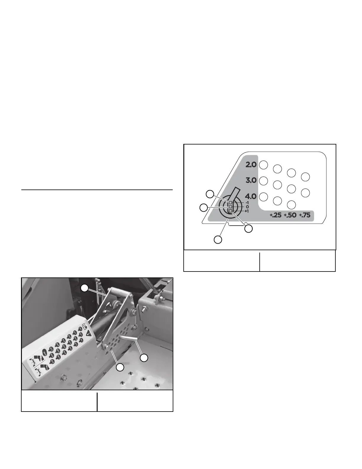
6. Use the illustration to establish which height adjusting
holes on the side decks to use. Figure 3-14
Height of Cut Range:
A. With the side deck wheels in the top hole (-1 on the
chart) the range of cut is 1.0" to 3.5" (25.4mm to
89mm).
B. With the side deck wheels in the middle hole (0 on
the chart) the range of cut is 2.0" to 4.5" (50.8mm to
114.3mm).
C. With the side deck wheels in the bottom hole (+1 on
the chart) the range of cut is 3.0" to 5.5" (76.2mm to
139.7mm).
7. On the side decks remove the hair pin from the clevis
pin and remove the pin from the height adjusting hole.
Slide the side wheel arm assembly until a slot aligns
with the desired hole. Slide the pin through the hole
and insert the hair pin. Figure 3-15 & Figure 3-16
8. Unbolt the side deck wheel and move it to the correct
hole. Retighten the nut. Figure 3-17
9. Repeat steps 7 and 8 for the other three side deck
adjusting locations.
A. Transport lever
B. Adjusting plate
C. Pin
Figure 3-13
A. Side deck wheel
B. Top hole
C. Middle hole
D. Bottom hole
Figure 3-14
 Loading...