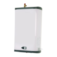
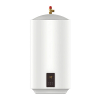
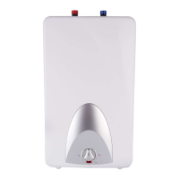
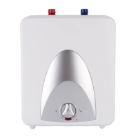
Plumbing connections
Connect ALL the plumbing valves in the sequence shown in diagram 1.
The cold water inlet to the heater is marked BLUE and the hot water outlet is marked RED.
Observe flow direction arrows on supplied valves.
•
The drain valve must be fitted close to the COLD inlet to allow drain down if necessary.
•
An isolating valve should be fitted UPSTREAM of all of the valves to allow the heater to be maintained
without impacting on other facilities.
•
Do NOT fit a service or other valves between the heater and the pressure relief (safety) valve as this
could impede its correct operation.
•
The pressure reducing valve is factory set at 3 bar. If a balanced cold water draw off is required this should
be tee-ed off down stream of this valve.
•
A balanced cold water feed is recommended as it ensures hot and cold water is supplied at the same
pressure. Some mixer taps and thermostatic showers require hot and cold water to be to be at the same
pressure for correct operation.
•
The expansion vessel supplied must be supported using a bracket or similar fixing. Do not rely on the
pipework alone – it will not be strong enough. The orientation of the vessel is not important.
•
When all valves are correctly fitted, open a hot tap and wait until the water flow is steady and without
traces of air. Close the tap to allow the system to reach full pressure and carefully check system for leaks.
Control valves may be supplied loosely connected for identification purposes, but these joins have
not been leak tested. This must be done at installation.
It is essential to also check the temperature pressure reflief valve connection to the heater for leaks.
Note that a leak from the temperature and pressure reflief vlve may not be immediately obvious, as
the connection is at the top of the heater and leaking water may in the first instance run down the
pipework and collect in the heater insulation.
Discharge pipe connections
This product falls within the scope of Building Regulation G3 which stipulates certain conditions relating to
the way any water discharge from relief valves is transported away.
These conditions are designed to ensure that any discharge will not present a hazard to people or to property,
and that any discharge is clearly visible so that the underlying cause is likely to be rectified promptly.
The essential requirement of G3 in relation to water discharge is that the discharge pipe MUST terminate in a
safe, visible position.
In achieving this aim the G3 regulations strongly recommended that:
•
The tundish is located within 500mm of the Temperature and Pressure Relief valve and it is wherever
possible oriented vertically. It must be visible to occupants and positioned away from electrical devices.
•
The discharge pipe has a vertical fall of at least 300mm immediately below the tundish.
•
The discharge pipe below the tundish is at least 22mm diameter (i.e. one size larger than the Temperature
and Pressure Relief valve outlet).
•
The discharge pipe should be as straight and as short as is possible and positioned away from
electrical components.
 Loading...