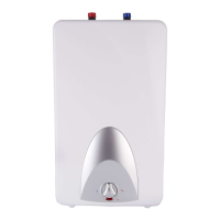
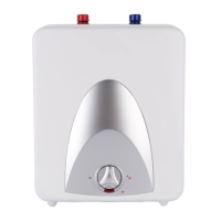
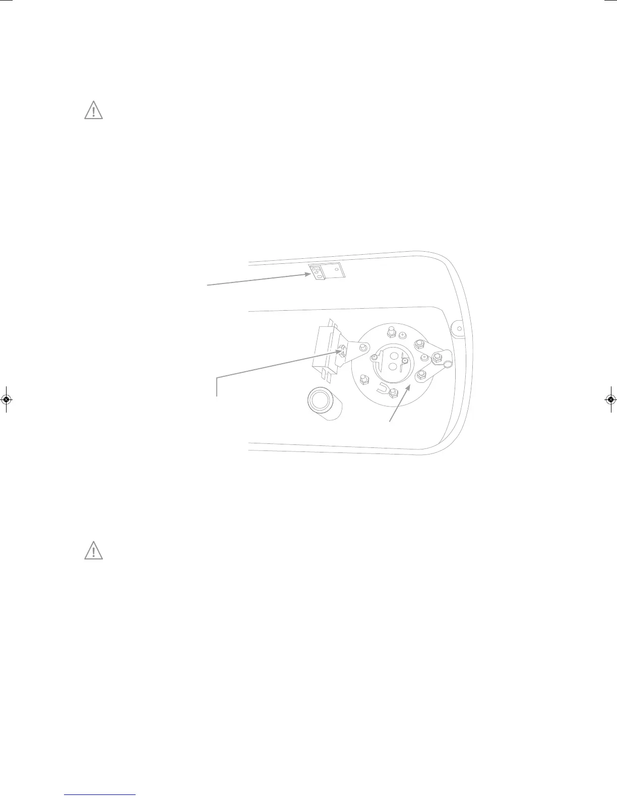
All maintainable electrical components are located under a plastic cover that is next to the inlet and outlet
pipes and held in position with two small screws. Remove screws and lower cover to provide access to
components. See diagram below for electrical parts identification.
If replacing electrical parts take particular attention to ensure that the earthing connections
(green/yellow) to the element flange and thermostat housing are sound.
Thermal cut-out reset
This unit contains a manually re-settable thermal cut-out that will switch the power off if the temperature
reaches an abnormally high level. To reset the cut-out the press button as shown in Diagram 4.
De-scaling procedure
If scale is allowed to build up heater performance will suffer and the life of the product will be reduced.
The effects of limescale are excluded from any warranty.
To de-scale the heater, gain access to the element following the instructions set out in section 10.
•
Remove thermostat and thermal cut-out bulbs from respective pockets and unscrew the 6 nuts holding
the element flange in position. Withdraw element.
•
Remove scale carefully. If necessary, dip element in a de-scaling solution available from DIY or plumbing
outlets. Do not allow electrical connections to become wet.
•
It is not normally necessary (or practical) to attempt to remove any scale from the tank walls.
•
Refit element and follow commissioning instructions as per section 8.
Temperature and
Pressure Relief Valve
POWERFLOW
Hot
Drain Cock
To Drain (Waste)
Pressure
(Expansion)
Relief Valve
Expansion
Vessel
Check
Valve
Balanced
Cold W ater
Draw O
Pressure
Reducing V alve
Service
Valve
Cold W ater
Mains
Diagram 1
B
A
Diagram 2
Model
Vertical
Bolt
Spacing A (mm)
Horizontal Bolt
Spacing B (mm)
PF30L 270320
PF50L 52
0320
PF90L 430320
Safety Device
Tundish
600mm MAXIMUM
Metal Discharge Pipe (D1) from
Temperature Relief to Tundish
Discharge Below
Fixed Grating
300mm MINIMUM
Metal Discharge Pipe (D2) from
Tundish with Continuous Fall
Fixed Grating
Trapped Gully
Sizing of D2 Copper Discharge pipe for common temperature relief valve outlet size
Valve
outlet
size
Minimum size of
discharge pipe (D1)
Minimum size of
discharge pipe (D2)
from Tun di s h
Maximum resistance allowed,
expressed as a length of straight
pipe (I.E. no elbows or bends)
Resistance
created by each
elbow or bend
m8.0m9otpumm22mm512/1G
28mm up to 18m 1.0m
m4.1m72ot*mm53
Diagram 4
Element ange -
Remove to access anode
Thermostat
Thermal cutout -
Press here to reset
H
Diagram 3
WD
 Loading...