Plan your installation carefully and choose a suitable position for the heater, allowing suitable space for
accessories such expansion vessels, pipework and subsequent maintenance.
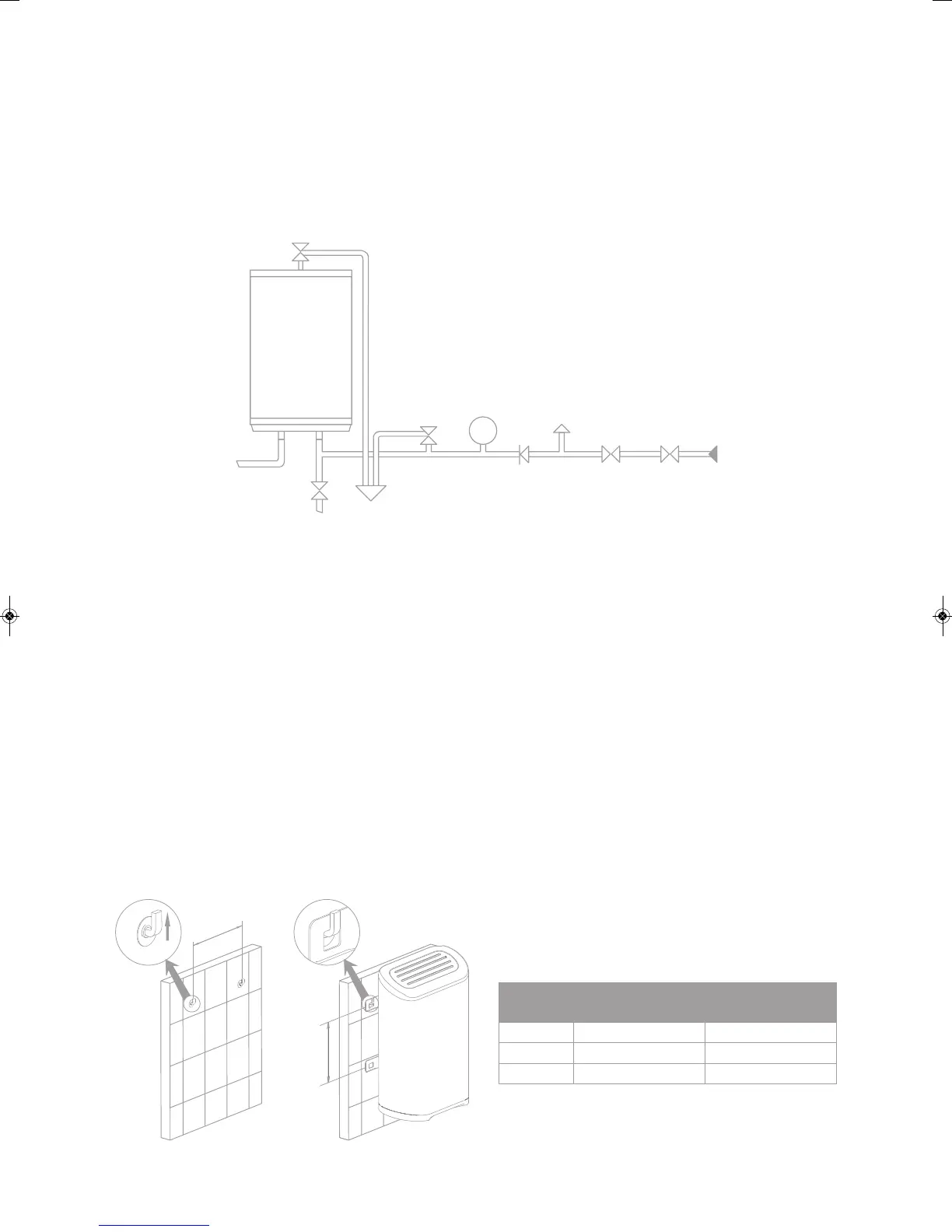
See schematic Diagram 1 for the correct relative positions of the components.
•
Fit all the components supplied, components may be supplied loose or connected to a mainfold.
The manifold aids installation but does not alter the relative positions of the components.
•
Do not remove the factory fitted temperature and pressure relief valve.
•
Ensure in particular that there are no valves of any kind between the expansion relief vlave and the heater.
•
Allow at least 400mm of space above and below the unity to permit for maintenance.
•
Observe flow direction arrows on components.
Wall mounting
Drill holes for supplied heavy duty bolts to wall at the spacings shown in the table below (also See Diagram 2).
Insert bolt hooks and tighten ensuring that they are secure then hang heater on the protruding hooks.
Temperature and
Pressure Relief Valve
POWERFLOW
Hot
Drain Cock
To Drain (Waste)
Pressure
(Expansion)
Relief Valve
Expansion
Ve ss el
Check
Valve
Balanced
Cold W ater
Draw O
Pressure
Reducing V alve
Service
Valve
Cold W ater
Mains
Diagram 1
B
A
Diagram 2
Model
Ve
rtical
Bolt
Spacing A (mm)
Horizontal Bolt
Spacing B (mm)
PF30L 270320
PF50L 52
0320
PF90L 430320
Safety Device
Tundish
600mm MAXIMUM
Metal Discharge Pipe (D1) from
Temperature Relief to Tundish
Discharge Below
Fixed Grating
300mm MINIMUM
Metal Discharge Pipe (D2) from
Tundish with Continuous Fall
Fixed Grating
Trapped Gully
Sizing of D2 Copper Discharge pipe for common temperature relief valve outlet size
Valve
outlet
size
Minimum size of
discharge pipe (D1)
Minimum size of
discharge pipe (D2)
from Tundish
Maximum resistance allowed,
expressed as a length of straight
pipe (I.E. no elbows or bends)
Resistance
created by each
elbow or bend
m8.0m9otpumm22mm512/1G
28mm up to 18m 1.0m
m4.1m72ot*mm53
Diagram 4
Element ange -
Remove to access anode
Thermostat
Thermal cutout -
Press here to reset
H
Diagram 3
WD
Temperature and
Pressure Relief Valve
POWERFLOW
Hot
Drain Cock
To Drain (Waste)
Pressure
(Expansion)
Relief Valve
Expansion
Ve ss el
Check
Valve
Balanced
Cold W ater
Draw O
Pressure
Reducing V alve
Service
Valve
Cold W ater
Mains
Diagram 1
B
A
Diagram 2
Model
Vertical Bolt
Spacing A (mm)
Horizontal Bolt
Spacing B (mm)
PF30LC
PF50LC
PF90LC
430320
Safety Device
Tundish
600mm MAXIMUM
Metal Discharge Pipe (D1) from
Temperature Relief to Tundish
Discharge Below
Fixed Grating
300mm MINIMUM
Metal Discharge Pipe (D2) from
Tundish with Continuous Fall
Fixed Grating
Trapped Gully
Sizing of D2 Copper Discharge pipe for common temperature relief valve outlet size
Valve
outlet
size
Minimum size of
discharge pipe (D1)
Minimum size of
discharge pipe (D2)
from Tundish
Maximum resistance allowed,
expressed as a length of straight
pipe (I.E. no elbows or bends)
Resistance
created by each
elbow or bend
m8.0m9otpumm22mm512/1G
28mm up to 18m 1.0m
m4.1m72ot*mm53
Diagram 4
Element ange -
Remove to access anode
Thermostat
Thermal cutout -
Press here to reset
H
Diagram 3
WD
Powerflow_Layout 1 28/06/2015 10:09 Page 3
 Loading...