6 / 10
POWERING THE UNIT 5.2.
When power is applied, the unit will start up automatically. The LCD will scroll through the boot diagnostics and display the serial numbers, software version and
model types for the amplifier and transducer.
The selected Display Mode will be visible with a measurement.
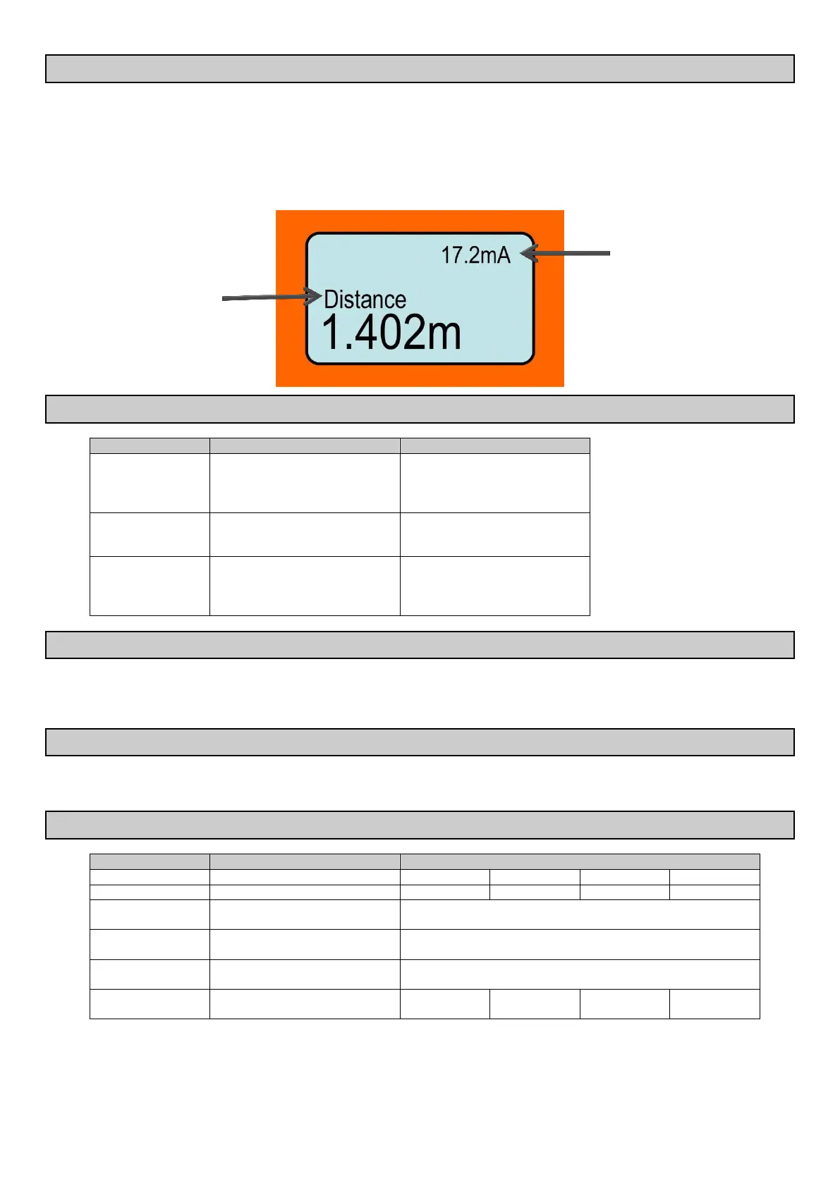
The top right hand corner diagnostic indicates either the operating mode or the current output.
The Microflex-D unit will re-scan for the level whenever it is powered up. The image below shows the elements of the standard display:
INTERFACE 5.3.
Press and release
Press and hold for 3 seconds
Access Main Menu
Select / Proceed
Access AutoSet Menu
Cancel / Return
Re-activate unit
Scroll between live diagnostics
Scroll between menu options
Adjust parameters
6. COMMISSIONING – SOFTWARE
Start up the unit. The Microflex-D uses automatic sensitivity control to detect and maintain the level. After applying power to the unit allow 20-30 seconds for the
unit to adjust to the application.
For best results ensure there is a liquid level present in the application, or a flat surface below the transducer.
MAIN MENU 6.1.
To access the Main menu press CAL
To access AutoSet menu press CAL and hold for 3 seconds
SETUP 6.2.
Set LCD measurement display mode
Adjust displayed measurement unit
Set Low-Level measurement point
(4mA)
Set High-Level measurement point
(20mA)
Adjust output response time &
smoothness
* Volume mode requires PC with Vision System II software. Consult Vision System II Manual