
J
Jessica Bennett PhDSep 9, 2025
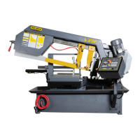
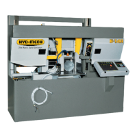
Why will the head not descend on my Hyd-Mech Saw?
- MMrs. Mary CaldwellSep 9, 2025
If the head of your Hyd-Mech Saw will not descend, check that the Feed Rate Valve is not fully closed. If the pointer is set on '0' or close to '0' in/min, turn the Feed Rate Knob counter clockwise to open the valve. Also, ensure that the Feed Force Limit is not set too low; increase the Feed Force Limit if necessary. Finally, check for any physical interference preventing the head from falling and remove any obstructions.