EasyManua.ls Logo

Hyd-Mech M-16A PLC 500 E600 User Manual

Hyd-Mech M-16A  PLC 500 E600
222 pages
To Next Page IconTo Next Page
Page #1 background imageLoading...
Page #1 background image
01
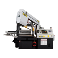
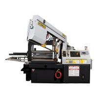
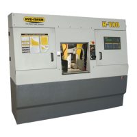
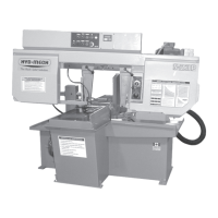
M-16A & M-20A PLC 500 E600 & PLC 100 E200
2003 Revision C
393060 December 2003
Effective T0503338
THANK YOU,
On behalf of everyone at HYD
.
MECH, I would like to thank and congratulate you on your decision to purchase a
HYD
.
MECH band saw.
Your new machine is now ready to play a key role in increasing the efciency of your operation, helping you to reduce cut-
ting costs while boosting quality and productivity.
To ensure you are maximizing the power and versatility of your new HYD
.
MECH band saw, please take the time to famil-
iarize yourself and your employees with the correct operation and maintenance procedures as outlined in this manual.
We sincerely appreciate the condence you have demonstrated in purchasing our product and look forward to building a
long and mutually benecial relationship.
Thank-you.
HYD
.
MECH GROUP LIMITED
P.O. BOX 1030, 1079 Parkinson Road
Woodstock, Ontario Canada, N4S 8A4
Phone: (519) 539-6341
Service 1-877-237-0914
Sales 1-877-276-SAWS(7297)
Fax (519) 539-5126
e-mail, info@hydmech.com

Table of Contents

Questions and Answers:

Hyd-Mech M-16A PLC 500 E600 Specifications

General IconGeneral
BrandHyd-Mech
ModelM-16A PLC 500 E600
CategorySaw
LanguageEnglish

Summary

Section 0, Safety Instructions

Safety Overview and Rules

Covers summary, basic rules, and responsibilities for safe operation.

Mandatory Information and Signatures

Details on required understanding and confirmation of safety procedures.

Owner and Personnel Responsibilities

Outlines duties for safe operation, maintenance, and training.

Safe Operation Practices

Guidelines for safe machine use, hazard labels, and fault reporting.

Personal Safety and Workplace

PPE, hearing protection, workplace cleanliness, and master disconnect.

Lock-Out Procedures

Safety measure for maintenance and repair isolation.

Section 1, Installation

Initial Setup and Anchoring

Covers lifting, foundation selection, leveling, and securing the machine.

Electrical and Fluid Connections

Power hook-up, phase order verification, and fluid level checks.

Head Height Check

Verification and adjustment of the head height relative to the infeed table.

Section 2, Operation Instructions

Blade Basics and Speed Control

Fundamentals of blade use, break-in, and variable speed adjustment.

Control Console and Startup

Overview of control panel functions and initial machine startup.

PLC Operation Modes

Explains manual, automatic, and single part cycle modes.

Job Programming and Automatic Operation

Setting up, editing, and running jobs in AUTO mode, including queues.

Cutting Parameters and Setup

Hydraulic feed control, cutting charts, and material-specific settings.

Coolant and Limit Settings

Adjusting coolant flow and setting head travel limits.

Section 3, Maintenance and Troubleshooting

Routine Maintenance Procedures

Includes lock-out, blade changing, lubrication, and cleaning guidelines.

General Troubleshooting

Addresses common machine problems and their solutions.

PLC and System Troubleshooting

Diagnosing PLC, encoder, and system-specific errors.

Calibration Procedures

Steps for calibrating length, head feed rate, and angle measurements.

Section 4, Electrical System

Electrical System Overview and Grounding

General electrical information and essential safety grounding procedures.

Component Lists

Lists of electrical components for M16A/M20A PLC500 across various voltages.

Electrical Schematics

Wiring diagrams for M16/20 A models with and without options.

Section 5, Hydraulic System

Hydraulic Component Lists

Component lists for M20 and M16 hydraulic assemblies.

Hydraulic Diagrams

Plumbing and schematic diagrams of the hydraulic system.

Section 6, Mechanical System

Key Mechanical Assemblies

Exploded views and component lists for blade brush, guide arm, and blade tension.

Other Mechanical Assemblies

Assemblies including pivot link, hydraulic tank, pump, conveyor, and vise.

Drive and Gearbox Assemblies

Exploded views and components for direct drive and gearbox systems.

Section 7, Options

Bundling Assembly

Description and components for the bundling vise option.

Other Optional Features

Variable vise pressure, out-of-stock switch, and laser sight.

Outboard Vise Assembly

Exploded view and component list for the outboard vise option.

Section 8, Specifications

Machine Specifications

Details capacity, dimensions, motors, pumps, and pressures in imperial/metric.

Machine Layouts

Physical arrangement and overall dimensions of the machines.

Section 9, Warranty

Warranty Information

Terms, conditions, coverage, and limitations of the product warranty.

Related product manuals