DD.026 ENG R(1)
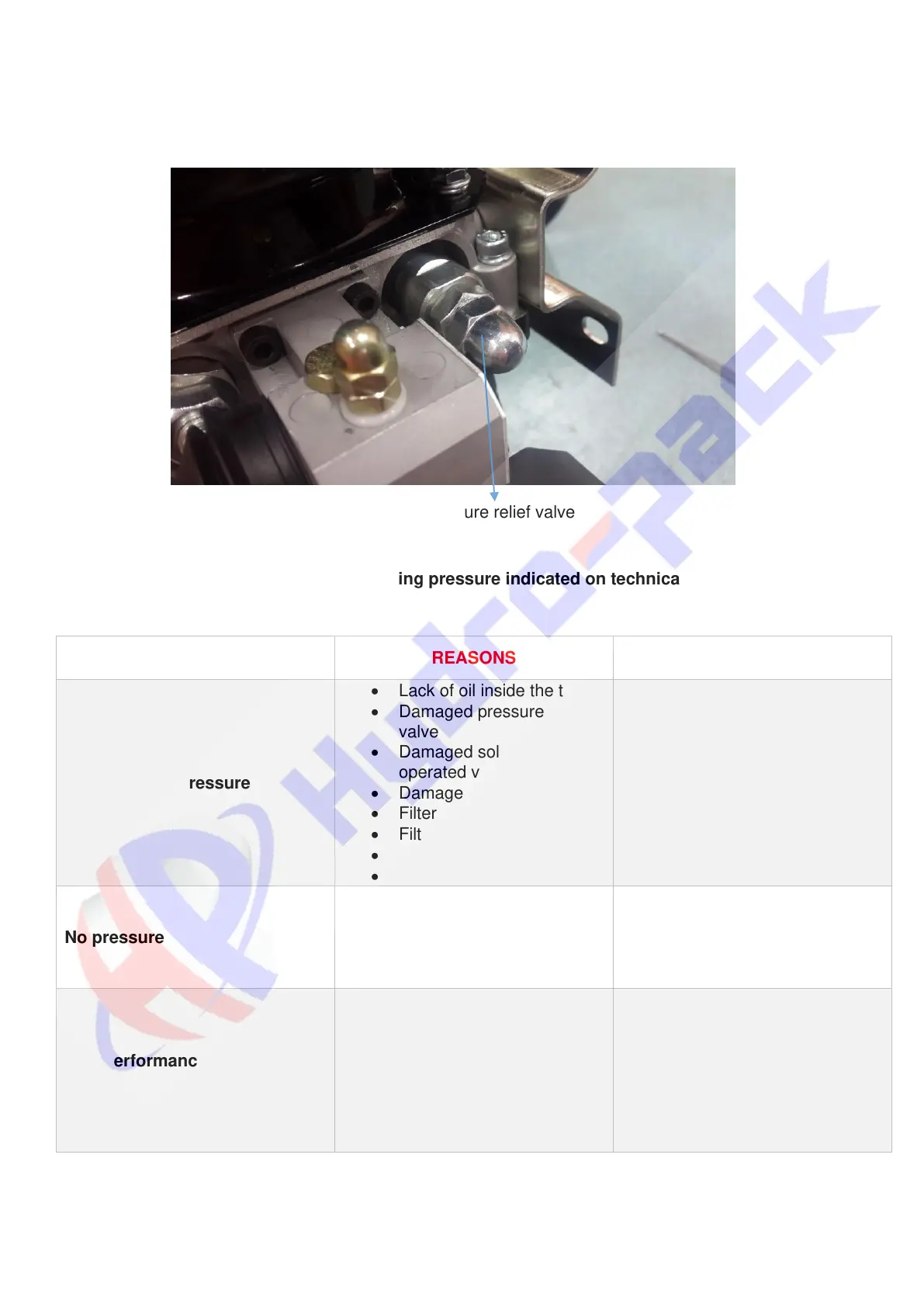
The hydraulic power is switched on and the adjusting screw is activated (clockwise to increase, anti-clockwise
to decrease) until it reaches the desired pressure. Then the nut is locked.
For detailed information, please refer to “DD.030 ENG R(0) Adjusting relief valve pressure on power pack”
document.
Photo 7. Pressure relief valve
Attention! Please do not pass max. working pressure indicated on technical drawing.
F3 PROBLEM SOLVING
• Lack of oil inside the tank
• Damaged pressure relief
valve
• Damaged solenoid
operated valve
• Damaged Hydraulic pump
• Filter pipe type is incorrect
• Filter is blocked
• Air on suction line
• Contamination
• The oil is filled up
• Readjustment of the relief
valve
• Replacement
• Replacement
• Replacement
• Replacement
• Elimination of the air
• Gear pump does’t operate
properly
• Electric motor rotation is
wrong
• Electric wiring is wrong
• Repair or replacement
• Make sure correct rotation
• Check wiring
Non-performance of the
function
• Damaged solenoid valve
• Damaged check valve
• Damaged pressure relief
valve
• Damaged hydraulic pump
All power packs are tested 100% before delivery to customer. Please kindly contact us for all questions.



 To Next Page