DD.026 ENG R(1)
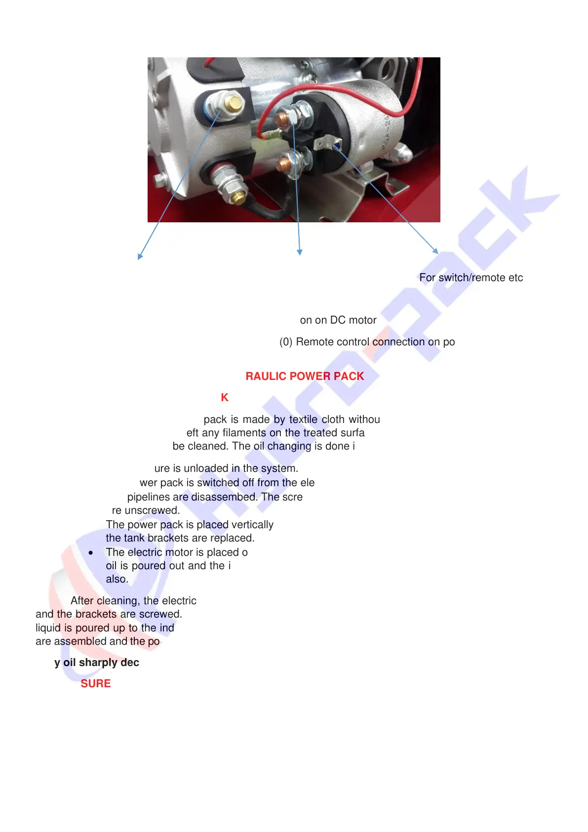
(-) from battery (+) from battery For switch/remote etc.
Photo 6. Connection on DC motor
For detailed information, please refer to “DD.043 R(0) Remote control connection on power units”
document.
SECTION F MAINTENANCE OF THE HYDRAULIC POWER PACK
F1 CLEANING OF THE POWER PACK
The cleaning of the power pack is made by textile cloth without using any cleaning substances or
solvents. The cloth should not left any filaments on the treated surfaces. Once yearly it is necessary the oil
to be changed in the tank to be cleaned. The oil changing is done in the following way:
• The pressure is unloaded in the system.
• The power pack is switched off from the electric installation.
• The pipelines are disassembed. The screws by which the power pack is fixed to the basement
are unscrewed.
• The power pack is placed vertically on the tank and the fixing screws are unscrewed and also
the tank brackets are replaced.
• The electric motor is placed outside together with the central manifold and the pump. The old
oil is poured out and the internal surface of the tank is cleaned. The suction filter is cleaned
also.
After cleaning, the electric motor with the central manifold are placed on the tank. The fixing screws
and the brackets are screwed. The assembled power pack is installed on its working position. The working
liquid is poured up to the indicated level on the stick. The air breather must be closed firmly. The pipelines
are assembled and the power pack is connected to electrical system in accordance to the way of application.
Dirty oil sharply decreases the life time of power pack.
F2 PRESSURE ADJUSTMENT
The pressure adjustment in the hydraulic power pack is made by means of pressure relief valve which
is built in on main manifold. The pressure adjustment is effected in the following order:
A pressure gauge is installed at port “P”. The nut of the adjusting screw is unlocked. The adjusting
screw is unscrewed up to its end.