DD.026 ENG R(1)
Electric motor
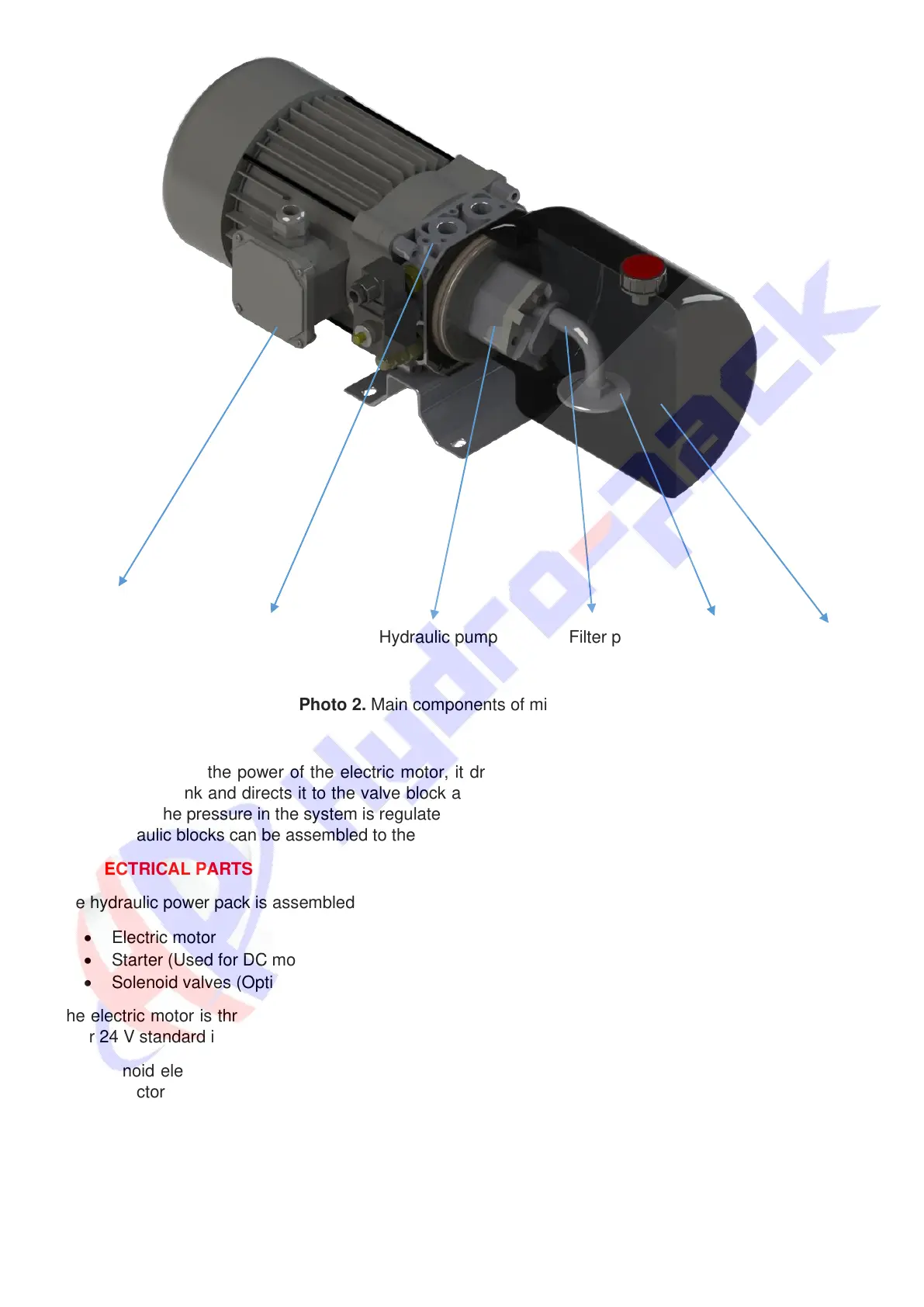
Central manifold Hydraulic pump Filter pipe Filter Oil tank
Photo 2. Main components of mini power pack
At switching on the power of the electric motor, it drives the gear pump. The pump sucks the working
liquid from the tank and directs it to the valve block and from there to the implementing components of the
power pack. The pressure in the system is regulated by the pressure relief valve which is built in main block.
Other hydraulic blocks can be assembled to the power pack according to customer’s demand.
C2 ELECTRICAL PARTS
The hydraulic power pack is assembled with:
• Electric motor
• Starter (Used for DC motors only)
• Solenoid valves (Optional)
The electric motor is three phase type or mono-phase for AC. Regarding DC motors, working voltages are
12 or 24 V standard in range.
The solenoid elements are cartridge type. Their coils can operate under voltages of 12, 24, 110 or 220 V.
The connectors are made under DIN 43650.