A placard has been provided with each control to eliminate problems encountered when the
spaside access hole is too large. Use the illustrations and instructions below to install the
spaside control provided with your system.
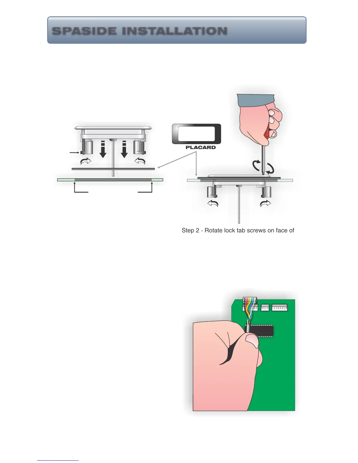
Step 1 - (If control cutout already exists, determine if
placard must be used. If existing cutout is sufficient,
disregard step 1.) Choose a location for the
spaside control. Using the template provided,
cut out a 2 5/8” X 6 3/8” hole. Clean area and
insert spaside control making sure tab locks
are rotated inward. (If placard is required, position and
secure using a water resistant silicone sealant.)
Step 2 - Rotate lock tab screws on face of
control clockwise to engage locks and secure
control into place.
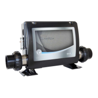
Step 3 - Remove protective film from display
windows, clean control surface with rubbing
alcohol and apply label. Connect spaside
control plug to circuit board as shown.
9
HT-2, Eco-3, 7 & 8 Series Spaside Controls:
IN IN
EXISTING HOLE
PLACARD
OUT OUT
SPASIDE INSTALLATION
TAB LOCK