7
LOW-FLOW SYSTEM CONFIGURATION
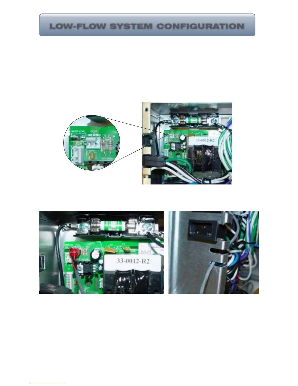
1. Locate the connection point
for the flow switch.
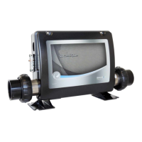
2. Connect the flow switch
connector to the connection
point making sure all pins are
covered.
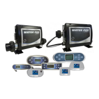
3. Route the flow switch cable
through an empty slot allocated
for small cables/cords.
The system may come equipped with a “Low-Flow” heater assembly and flow
switch. When a flow switch is supplied the connection of the switch to the
system is directly to the PCB (Printed Circuit Board). Below are details on
where and how to connect the flow switch to a CS7506 control system. The
connection point may differ on other control systems. When in doubt refer to
the wiring diagram location inside the control box cover for details and connect
accordingly to the pressure/flow switch connection point.