H-8000C
AC Powered Flush Valve
Installaon Instrucons
ISO 9001 Cer ed
H-8000C
AC Powered Flush Valve
Installa on Instruc ons
Installa on Instruc ons:
1. Prior to installa on, “DRY TEST” the unit for proper
opera ons. Loosen the Set Screws (1) using the allen
wrench provided and remove the Top Cap (2) from the
valve body by pulling it straight up.
2. Connect the AC Power Adapter (3) to the Control
Module (4) and plug it in to a working power outlet.
Push the RESET bu on and watch the indicator lights
on the Control Module (4) for the following pa ern:
Red, (click), Green, Red, Red. This indicates that the
electronics are func oning properly. If the indicator
lights do not blink, contact the factory or your local
Hydrotek representa ve.
3. Reinstall the Top Cap (2) onto the valve body and
ghten the Set Screws (1). Install the Stop Valve (5) to
the supply line using a Hydrotek Sweat Kit (op onal).
4. Connect the valve body to the Stop Valve (5) using the
Slip Joint Nut (6).
5. A ach the Vacuum Breaker (7) and Tailpiece (9) to the
valve body using the Lock Nut (8). Secure the Tailpiece
(9) to the plumbing fi xture using the provided Spud
Coupling (10).
6. Turn the water on through the Stop Valve (5) and check
for leaks. Push and hold the Override Bu on (11) for
30 seconds and check the fi xture for over ow. Adjust
the water ow from the Stop Valve (5) for a smoother
ush.
7. TEST: Stand in front of the ush valve for 4 seconds,
then step away. The valve should ush automa cally. If
not, refer to the Troubleshoo ng Guide.
8. Flow rates are preadjusted from the factory. If minor
adjustments are needed, contact Hydrotek for further
details.
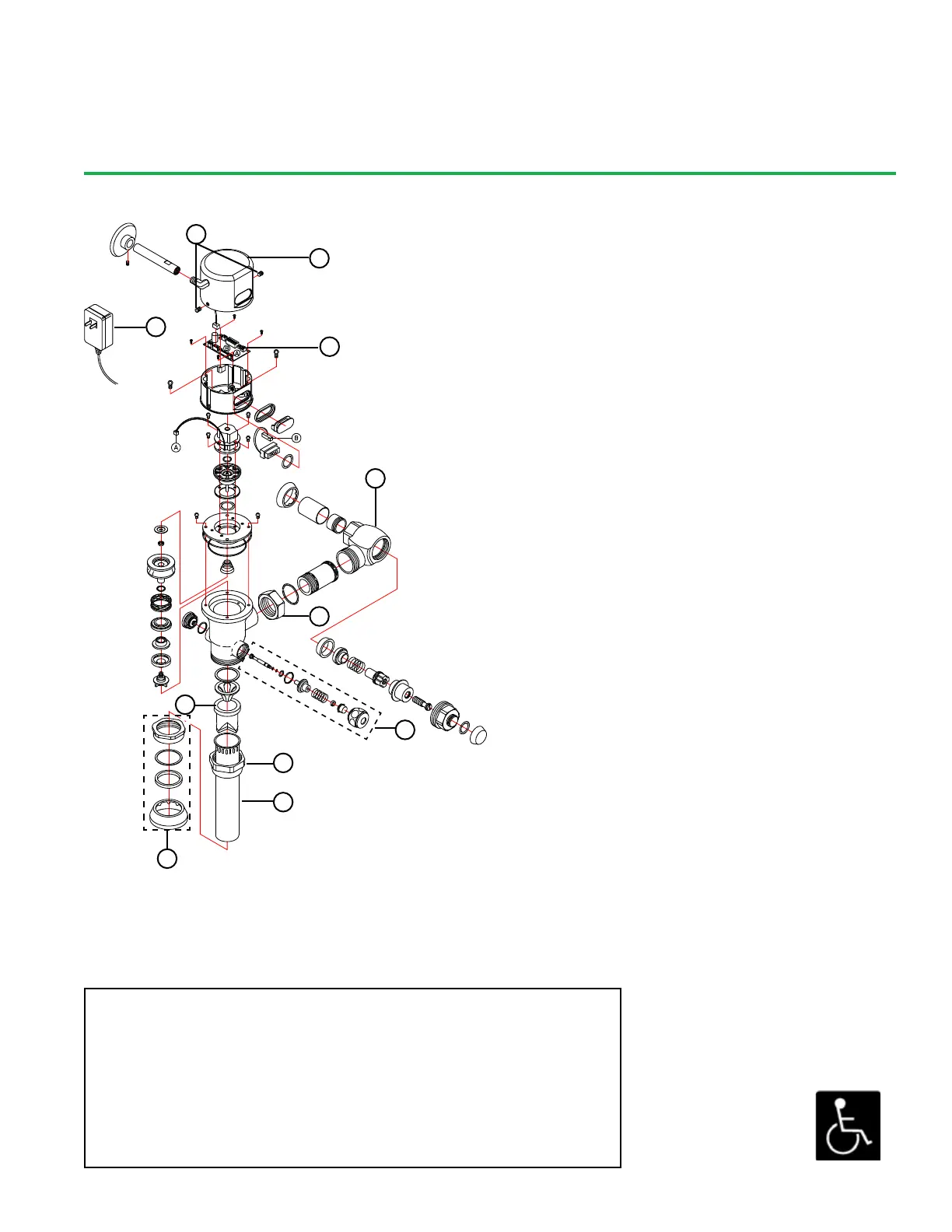
Parts:
1. Set Screws 7. Vacuum Breaker
2. Top Cap 8. Lock Nut
3. AC Power Adapter 9. Tailpiece
4. Control Module 10. Spud Coupling
5. Angle Stop 11. Override Bu on
6. Slip Joint Nut
HYDROTEK INTERNATIONAL, INC.
5055 Forsyth Commerce Rd., Ste 124
Orlando, FL 32807
800.922.9883 (Phone)
866.670.5580 (Fax)
www.hydrotekintl.com
6
1
2
3
4
5
11
7
8
9
10
 Loading...